Spetz Specs No. 1197: step-by-step system install guide
Subsurface Pond Aeration System Installation
The complete step-by-step guide made from Indy Farm Life's YouTube video, free on Spetz. For the video, a step-by-step player and answers to your questions, see the Subsurface Pond Aeration System Installation project page.
9 steps, 5 parts, 10 tools, 8 materials
Overview
The System
- Install the dual-diffuser Airmax PS20 1/2 HP subsurface pond aeration system.
- A shore-mounted compressor pushes air via 5/8 in weighted hoses to submerged sleds.
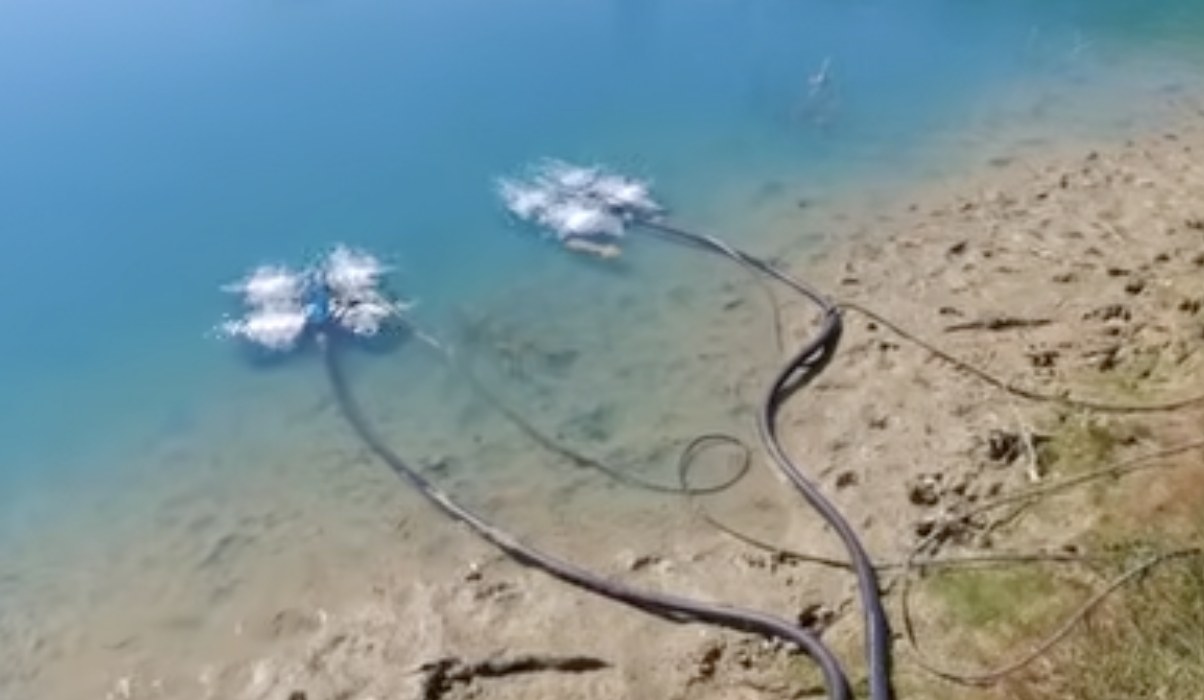
- Microscopic diffuser pores release fine bottom bubbles to circulate oxygen.
Why Do It Yourself
- Manuals omit diffuser assembly order and thread-sealing rules protecting microscopic pores.
- Shoreline conduit sleeves and retrieval ropes prevent mower damage and broken fittings.
What It Takes
- Allow 25 minutes with shoreline power, or an afternoon if trenching.
- Use shovels, a level, a nut driver, and a motorized boat.
- Have a shore helper feed heavy weighted airline while boating.
- Have a licensed electrician wire the permanent subpanel and buried feeder.
What Decides Success
- Seal plastic diffuser threads with PTFE tape only, never pipe paste.
- Balance the cabinet manifold valves so air reaches the deeper diffuser.
- Gradually increase daily run times on older ponds to prevent fish kills.
The system at a glance
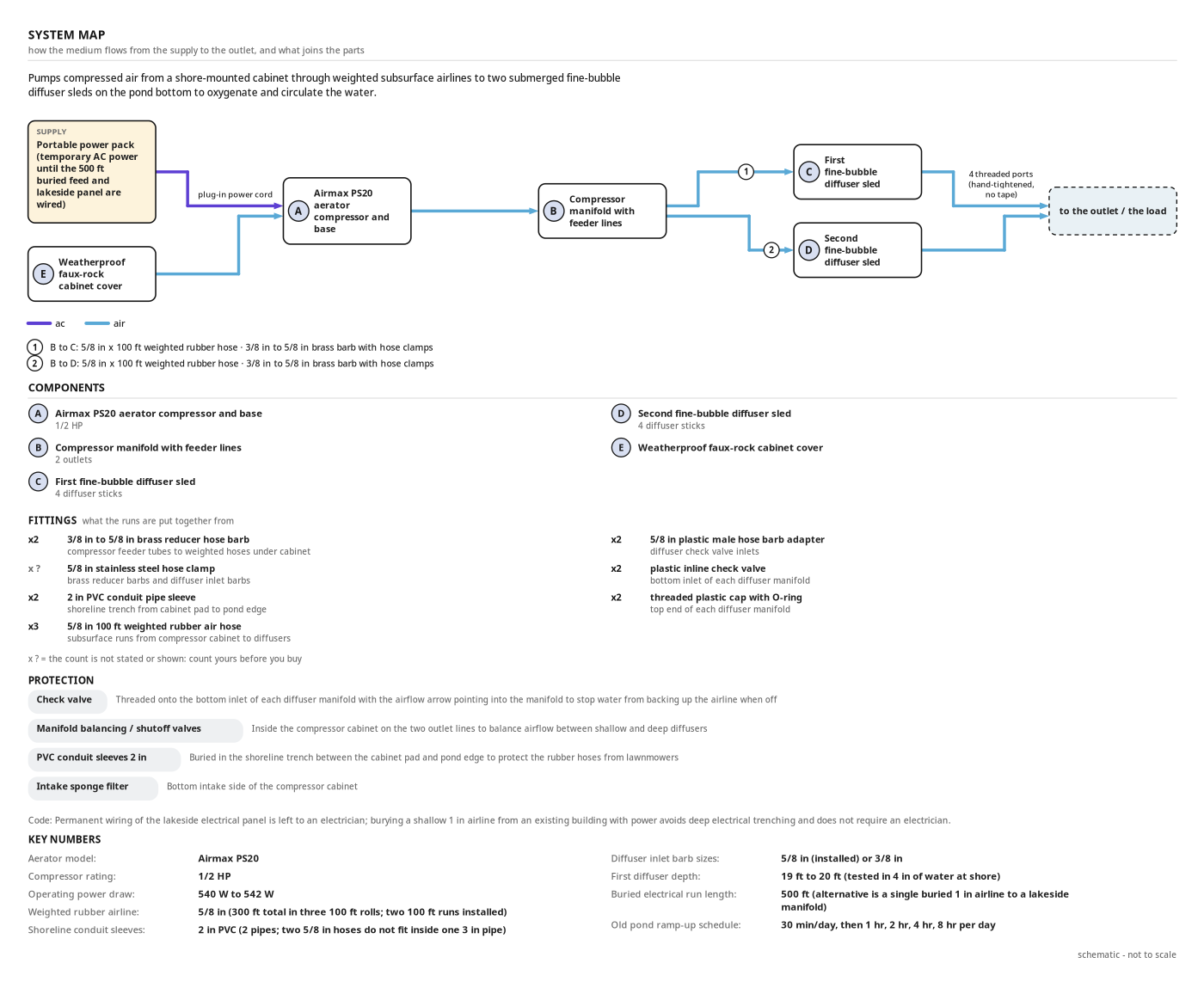
- Pumps compressed air from a shore-mounted cabinet through weighted subsurface airlines to two submerged fine-bubble diffuser sleds on the pond bottom to oxygenate and circulate the water.
- Supply: Portable power pack (temporary AC power until the 500 ft buried feed and lakeside panel are wired)
- supply → Airmax PS20 aerator compressor and base: ac, cable, plug-in power cord
- Weatherproof faux-rock cabinet cover → Airmax PS20 aerator compressor and base: air, direct
- Airmax PS20 aerator compressor and base → Compressor manifold with feeder lines: air, direct
- Compressor manifold with feeder lines → First fine-bubble diffuser sled: air, hose, 5/8 in x 100 ft weighted rubber hose, 3/8 in to 5/8 in brass barb with hose clamps at cabinet; 5/8 in plastic barb with Teflon tape and two hose clamps at diffuser check valve
- Compressor manifold with feeder lines → Second fine-bubble diffuser sled: air, hose, 5/8 in x 100 ft weighted rubber hose, 3/8 in to 5/8 in brass barb with hose clamps at cabinet; 5/8 in plastic barb with Teflon tape and two hose clamps at diffuser check valve
- First fine-bubble diffuser sled → out: air, direct, 4 threaded ports (hand-tightened, no tape)
- Second fine-bubble diffuser sled → out: air, direct, 4 threaded ports (hand-tightened, no tape)
- Protection: Check valve, Threaded onto the bottom inlet of each diffuser manifold with the airflow arrow pointing into the manifold to stop water from backing up the airline when off
- Protection: Manifold balancing / shutoff valves, Inside the compressor cabinet on the two outlet lines to balance airflow between shallow and deep diffusers
- Protection: PVC conduit sleeves, 2 in, Buried in the shoreline trench between the cabinet pad and pond edge to protect the rubber hoses from lawnmowers
- Protection: Intake sponge filter, Bottom intake side of the compressor cabinet
- Aerator model: Airmax PS20
- Compressor rating: 1/2 HP
- Operating power draw: 540 W to 542 W
- Weighted rubber airline: 5/8 in (300 ft total in three 100 ft rolls; two 100 ft runs installed)
- Shoreline conduit sleeves: 2 in PVC (2 pipes; two 5/8 in hoses do not fit inside one 3 in pipe)
- Diffuser inlet barb sizes: 5/8 in (installed) or 3/8 in
- First diffuser depth: 19 ft to 20 ft (tested in 4 in of water at shore)
- Buried electrical run length: 500 ft (alternative is a single buried 1 in airline to a lakeside manifold)
- Old pond ramp-up schedule: 30 min/day, then 1 hr, 2 hr, 4 hr, 8 hr per day
Codes
- Permanent wiring of the lakeside electrical panel is left to an electrician; burying a shallow 1 in airline from an existing building with power avoids deep electrical trenching and does not require an electrician.
Health and safety
Trenching and Heavy Equipment
- Contact utility locators before digging the trench with the backhoe loader to avoid striking buried power lines or pipes.
- Keep bystanders clear of the backhoe swing radius and the compact tractor H180 loader bucket while moving soil and crushed stone.
- Operate the backhoe, compact tractor, and golf cart at low speeds on wet or sloped pond banks to prevent rollovers.
Electrical and Pump Hazards
- Have a licensed electrician complete all permanent subpanel and buried electrical feeder terminations for the 1/2 HP compressor.
- Keep the 2600W portable power station on dry ground well back from the trench and pond edge during testing and pumping.
- Unplug the submersible utility pump before handling it in the flooded trench, and never touch power cords with wet hands.
Boat and Water Safety
- Clamp the electric trolling motor tightly to a solid transom before towing heavy 5/8 in weighted rubber hoses under load.
- Keep your weight centered in the jon boat when lowering the diffuser sleds and weighted airlines over the side.
- Feed the retrieval rope and 100 ft weighted hoses smoothly so coils cannot snag your feet or pull you overboard.
Heavy Lifting and Sharp Edges
- Bend at the knees when lifting the 100 ft rolls of weighted rubber air hose and the compressor assembly.
- Wear protective gloves when tightening stainless steel worm-drive hose clamps with a screwdriver or nut driver to avoid sliced knuckles.
- Watch your footing around open trenches, wet mud, and 2 in PVC conduit pipes to prevent slips and ankle injuries.
Checks before you start
- Check the pond 120V AC outlet or stage a 2600W portable power station for testing.
- Have a licensed electrician wire the permanent 500 ft buried feeder and subpanel.
- Get two 2 in PVC conduits; two 5/8 in weighted hoses cannot fit in one 3 in pipe.
- Confirm two 3/8 in to 5/8 in brass cabinet barbs and two 5/8 in plastic diffuser barbs.
- Check the boat transom for rot and clamp the motor tight before pulling heavy weighted hose.
- Pick a shaded, well-drained pad site, like under a solar array.
Tools
- Golf cart (utility vehicle) (optional)
- Backhoe loader (tractor loader backhoe, Case, 580 Super K) (optional)
- Submersible utility pump (sump pump with discharge hose) (optional)
- Compact utility tractor with loader (compact tractor, John Deere, 4052R, H180 front-end loader) (optional)
- Round-point shovel (hand shovel)
- Trenching shovel (narrow-blade shovel) (optional)
- Torpedo level (spirit level, Craftsman)
- Portable power station (battery power pack, Bluetti, Elite 200 V2, 2600W, 2073.6Wh) (optional)
- Screwdriver / nut driver (hand driver)
- Jon boat with electric trolling motor (utility boat)
Materials
- Pond aeration system (1 kit, subsurface pond aerator kit, Airmax, PS20, 1/2 HP, 2 diffuser heads)
- Weighted rubber air hose (300 ft (3 rolls), weighted subsurface airline, 5/8 in ID, 5/8 in diameter, 100 ft per roll)
- Crushed stone (gravel)
- PVC conduit pipe (2 pipes, PVC conduit / drain waste pipe, 2 in, 2 in diameter)
- Brass hose barbs (2, barbed reducer fittings, 3/8 in to 5/8 in)
- Hose clamps (6 to 8, stainless steel worm-drive hose clamps, For 5/8 in ID (approx. 1 in OD) weighted hose)
- Retrieval rope (2 lengths, utility rope)
- Teflon thread seal tape (1 roll, PTFE plumber's tape)
Hardware
| Hardware | Size | Count | Used in steps |
|---|---|---|---|
| 3/8 in to 5/8 in Brass hose barbs | 2 | 4 | |
| 5/8 in ID hose size Hose clamps | 6 | 4, 6 |
Finishes & supplies, in the order they go on
| Product | What it does | Mix & coats | Dry time | Applied with |
|---|---|---|---|---|
| Teflon thread seal tape | Seals the diffuser manifold's threaded plastic cap, inline check valve and 5/8 in hose barb without clogging microscopic pores. | Hand-wrapped onto male plastic threads |
Components
| Part | Name | Qty | Size | Notes |
|---|---|---|---|---|
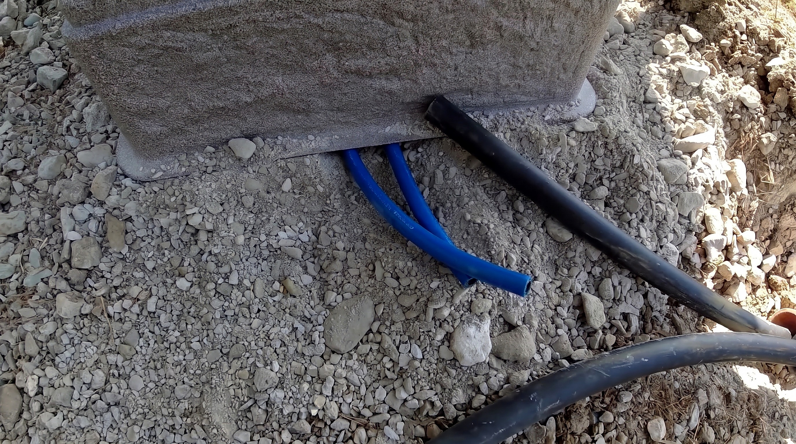
| A | Airmax PS20 aerator compressor and base | x1 | 1/2 HP | Set on a leveled crushed stone pad under the solar panels; hose-clamp connections tuck into the base cavity. |
| B | Compressor manifold with feeder lines | x1 | 2 outlets | Located inside the cabinet with individual valves and two flexible feeder lines exiting through the bottom and side. |
| C | First fine-bubble diffuser sled | x1 | 4 diffuser sticks | Includes blue manifold, top O-ring cap, bottom check valve, sled base, 4 perforated sticks, and retrieval rope; placed at 19 ft. |
| D | Second fine-bubble diffuser sled | x1 | 4 diffuser sticks | Assembled hand-tight with Teflon tape on cap, check valve, and 5/8 in barb (no paste); deployed 100 ft out with retrieval rope. |
| E | Weatherproof faux-rock cabinet cover | x1 | Encloses the compressor with a bottom intake sponge filter and side exhaust port; keep gravel clear of openings. |
Step by step
Step 1: Excavate and Drain the Utility Trench
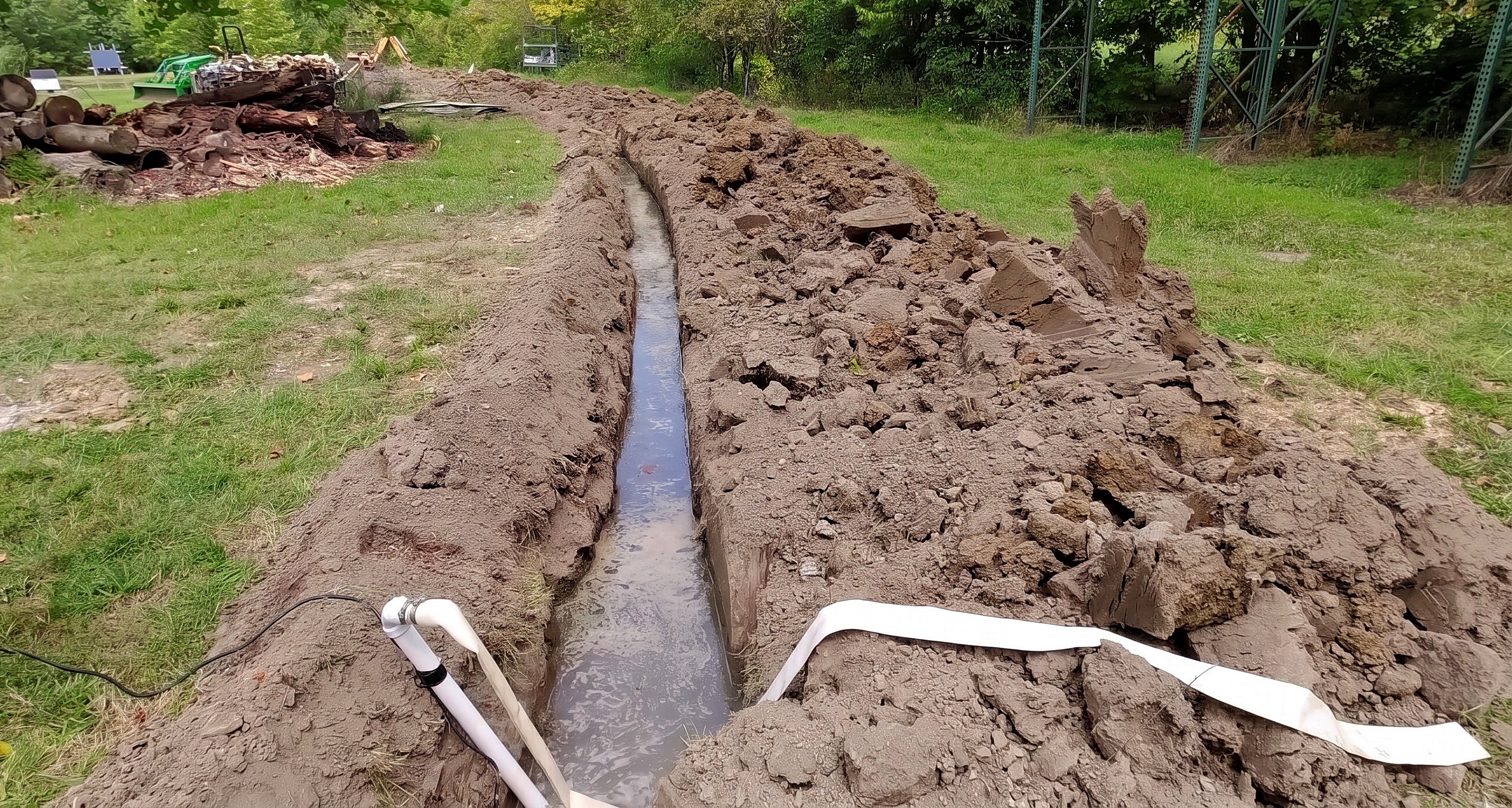
Drain standing water and dig the 500 ft utility trench from barn to pond.
You'll need: Submersible utility pump, Backhoe loader
- 1.1 Pump standing water from the trench
- Set a submersible utility pump and discharge hose in the flooded trench.
- Pump standing water clear of the work area before digging the rest.
- 1.2 Excavate the utility trench with a backhoe
- Dig the 500 ft trench from power source to pond with a backhoe.
- Leave permanent subpanel feeder wire connections to a licensed electrician.
Key measurements
- Buried electrical trench length: 500 ft from barn to pond panel
- Tip: Bury a shallow 1 in airline from an existing outlet if lakeside power is unneeded.
- Heads up: Have a licensed electrician complete permanent subpanel and buried feeder terminations.
Step 2: Prepare the Gravel Pad and Conduit Trench
Build a level gravel cabinet pad, lay two 2 in PVC shoreline sleeves, and stage temporary power.
Parts in this step: (A) Airmax PS20 aerator compressor and base, (B) Compressor manifold with feeder lines
You'll need: Golf cart, Compact utility tractor with loader, Round-point shovel, Trenching shovel, Torpedo level, Portable power station, Pond aeration system, Crushed stone, PVC conduit pipe
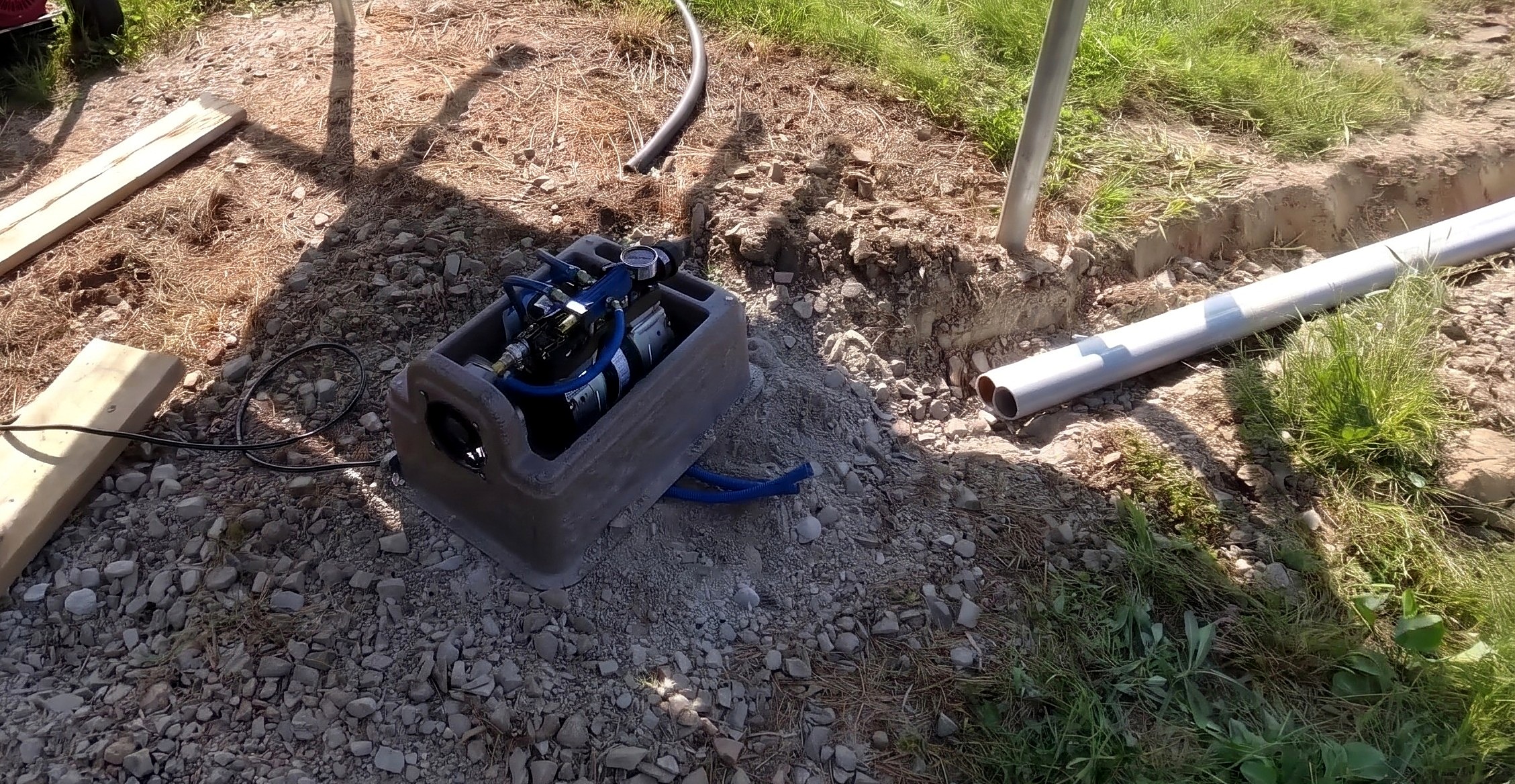
- 2.1 Spread and level crushed stone for the cabinet pad
- Dump crushed stone in shade, such as under a solar array.
- Spread the stone with a shovel and check the pad with a torpedo level.
- Set the Airmax PS20 aerator compressor and base (A) flat on the stone pad.
- 2.2 Lay dual 2-inch PVC conduit pipes in the shoreline trench
- Dig a shallow trench from the gravel pad to the water's edge.
- Lay two 2 in PVC conduit pipes side by side in the shoreline trench.
- Use one 2 in pipe per hose; two 5/8 in hoses cannot fit in one 3 in pipe.
- 2.3 Route the compressor feeder tubes and stage temporary power
- Route the two blue lines from compressor manifold with feeder lines (B) out the base bottom.
- Bend both flexible feeder lines sideways toward the PVC conduit tops.
- Set a portable power station by the pad for temporary AC power.
Key measurements
- Shoreline protective conduit diameter: 2 in PVC pipe, one per airline
- Tip: Shade the cabinet to keep sun and rain off the housing.
- Tip: Pack crushed stone under and around the base to deter nesting mice.
Before you move on: Level the compressor base on the gravel pad before connecting airlines.
Step 3: Uncoil and Sleeve the Weighted Airlines
Uncoil two 100 ft rolls of 5/8 in weighted rubber hose without kinks and push through the PVC sleeves.
You'll need: Weighted rubber air hose, PVC conduit pipe
- 3.1 Uncoil the weighted rubber hoses along the shoreline
- Unbox the 100 ft coil of 5/8 in weighted rubber air hose.
- Walk backward on the bank, twisting the hose to remove coil memory.
- Lay both 100 ft runs flat along the shoreline so they sink without kinking.
- 3.2 Push the weighted hose through the PVC conduit sleeve
- Push the cabinet end of each 5/8 in weighted hose up a 2 in PVC conduit.
- Pull both hose ends out the conduit tops by the compressor base.
Key measurements
- Weighted airline size: 5/8 in inside diameter, 100 ft roll
- Tip: Sleeve the bank hoses in PVC to guard against lawnmower blades.
Before you move on: Check both uncoiled 100 ft hoses on the bank have zero twists or loops.
Step 4: Connect Airlines to the Compressor Cabinet
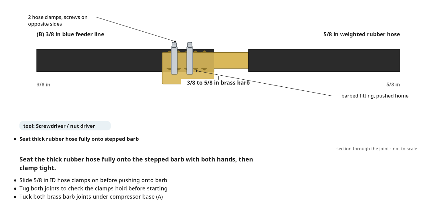
Join both 5/8 in weighted hoses to the 3/8 in blue compressor feeder tubes with brass reducer barbs and hose clamps.
Parts in this step: (B) Compressor manifold with feeder lines
You'll need: Screwdriver / nut driver, Weighted rubber air hose, Brass hose barbs, Hose clamps
- 4.1 Insert brass reducer barbs and clamp the hoses
- Slide stainless steel hose clamps over the 5/8 in weighted hoses and blue feeder lines.
- Push each brass reducer barb's 5/8 in end into a weighted rubber hose.
- Push each brass barb's 3/8 in end into a blue line from the compressor manifold with feeder lines (B).
- Tighten both hose clamps on each brass barb with a nut driver.
Key measurements
- Brass reducer barb size: 3/8 in feeder to 5/8 in weighted hose
- Tip: Seat the thick rubber hose fully onto the stepped barb with both hands.
Before you move on: Tug both joints to check the clamps hold before starting the compressor.
Step 5: Attach Retrieval Rope and Test First Diffuser
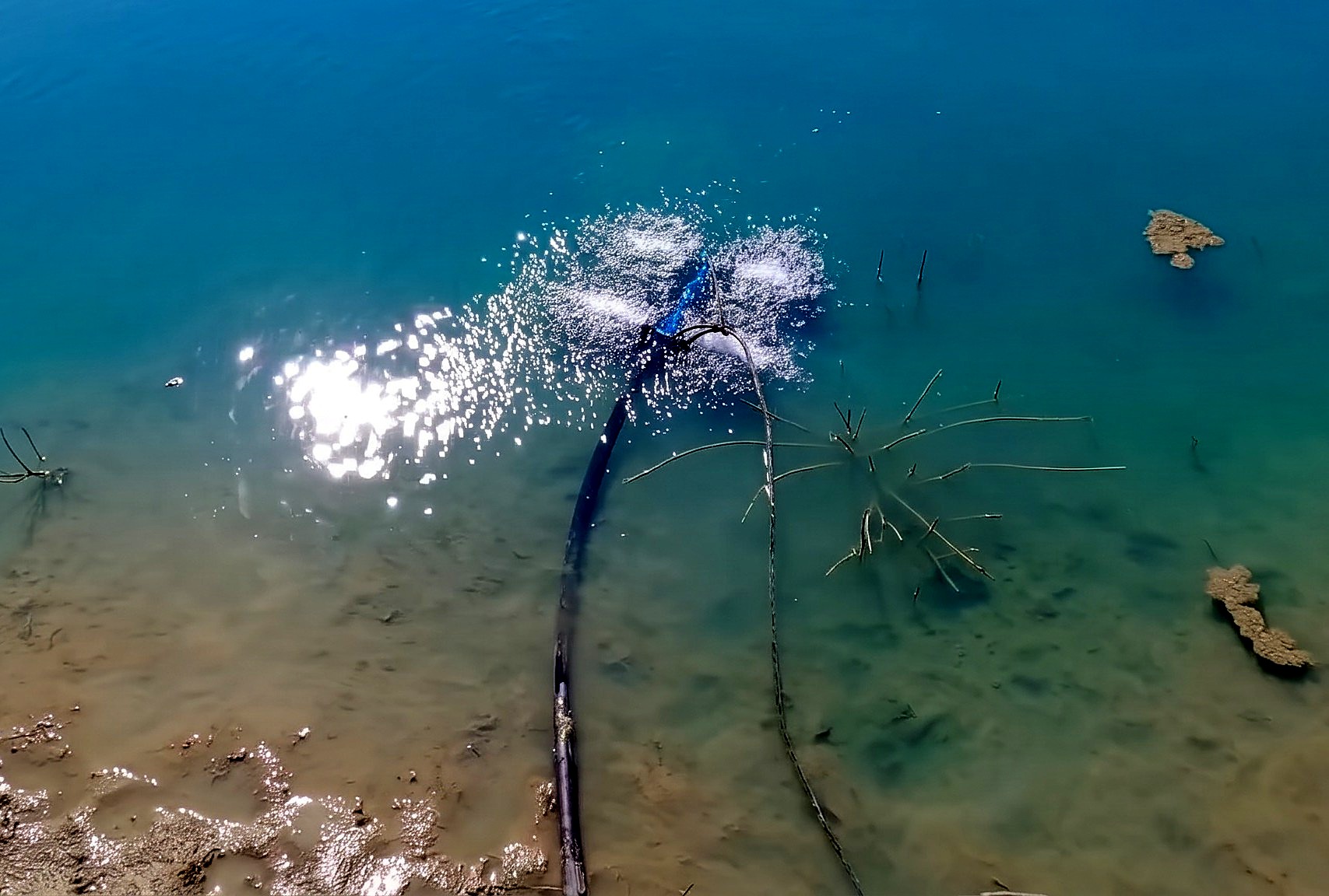
Tie a retrieval rope to the first diffuser sled and check fine-bubble output in shallow water.
Parts in this step: (A) Airmax PS20 aerator compressor and base, (C) First fine-bubble diffuser sled
You'll need: Portable power station, Pond aeration system, Retrieval rope
- 5.1 Tie a retrieval rope and submerge the first diffuser in shallow water
- Tie a retrieval rope to the first fine-bubble diffuser sled (C) center manifold.
- Turn on the portable power station and start the Airmax PS20 aerator compressor and base (A).
- Sink the first diffuser sled in 4 in of bank water to check fine bubbles.
Key measurements
- Shallow test depth: 4 in of shoreline water
- Tip: Lift the sled vertically by rope from a boat for future cleaning.
- Heads up: Never drag a silted-in diffuser sled by the air hose, or the plastic barb snaps.
Before you move on: Check even tiny bubbles rise across all four diffuser sticks before building the second sled.
Step 6: Assemble and Connect the Second Diffuser Sled
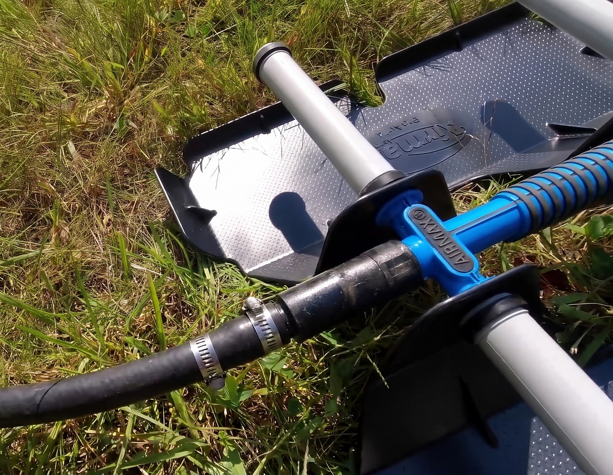
Build the second fine-bubble diffuser sled with PTFE tape and clamp it to the second weighted airline.
Parts in this step: (D) Second fine-bubble diffuser sled
You'll need: Screwdriver / nut driver, Pond aeration system, Weighted rubber air hose, Hose clamps, Teflon thread seal tape
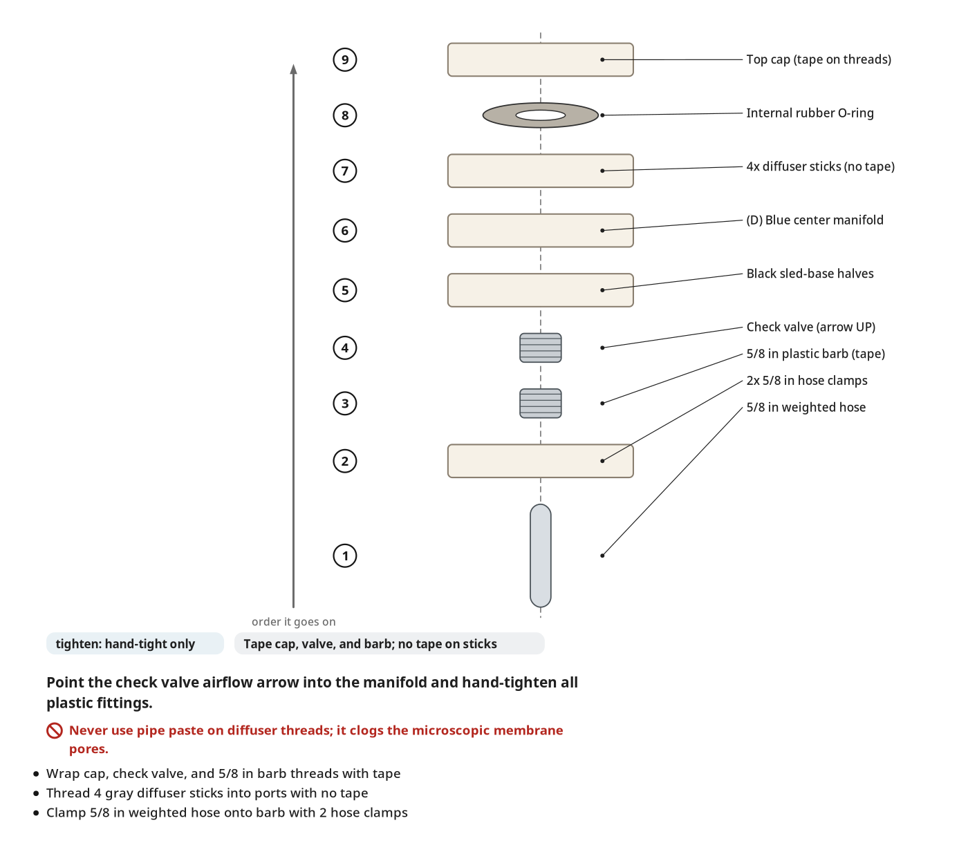
- 6.1 Seal and thread the top cap onto the diffuser manifold
- Unscrew the top cap and internal rubber O-ring from the second fine-bubble diffuser sled (D) manifold.
- Wrap the blue plastic manifold's top male threads with Teflon thread seal tape.
- Thread the O-ring cap onto the manifold hand-tight.
- 6.2 Tape and install the check valve and 5/8-inch hose barb
- Unscrew the black check valve from the blue manifold's bottom inlet.
- Wrap the manifold bottom male threads with Teflon tape, never pipe paste.
- Point the check valve airflow arrow into the manifold and thread on hand-tight.
- Wrap the 5/8 in plastic barb threads with Teflon tape and thread into the check valve.
- 6.3 Mount the black sled base and screw in the four diffuser sticks
- Fit both black plastic sled-base halves over the four manifold side ports.
- Thread the four gray perforated diffuser sticks into the ports without Teflon tape.
- Hand-tighten the four diffuser sticks until they clamp the sled base.
- 6.4 Clamp the second weighted airline onto the diffuser barb
- Slide two stainless steel hose clamps onto the second 5/8 in weighted hose end.
- Push the weighted hose fully onto the 5/8 in plastic diffuser inlet barb.
- Tighten both hose clamps on the barb with a nut driver.
Key measurements
- Diffuser inlet barb diameter: 5/8 in male thread to 5/8 in hose barb
- Tip: Put two hose clamps on the underwater diffuser barb so the heavy line cannot slip off.
- Heads up: Never use pipe paste on diffuser threads; it clogs the microscopic membrane pores.
- Heads up: Hand-tighten plastic manifold fittings; wrenches can crack the threads.
Before you move on: Check the black check valve arrow points into the blue diffuser manifold.
Step 7: Test Both Diffusers in Shallow Water
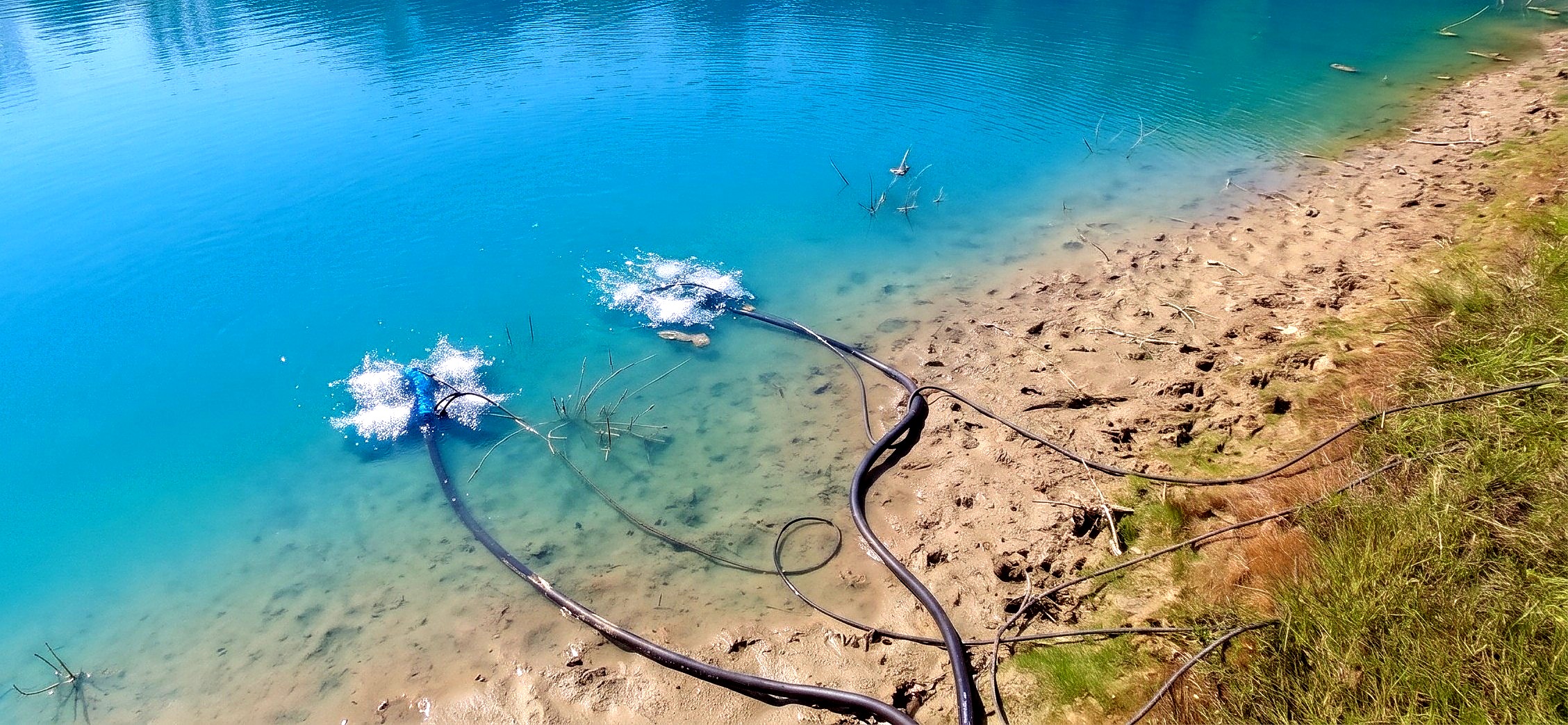
Tie a retrieval rope to the second diffuser sled and test both heads side by side ashore.
Parts in this step: (A) Airmax PS20 aerator compressor and base, (C) First fine-bubble diffuser sled, (D) Second fine-bubble diffuser sled
You'll need: Pond aeration system, Retrieval rope
- 7.1 Tie a rope to the second diffuser and place it in the pond
- Tie a retrieval rope to the center manifold of the second fine-bubble diffuser sled (D).
- Set the second sled in shallow water beside the first fine-bubble diffuser sled (C).
- 7.2 Switch on the compressor to verify both diffusers bubble
- Switch on the Airmax PS20 aerator compressor and base (A).
- Check both submerged diffuser sleds make steady fine-bubble clouds along the bank.
- Tip: Use a sinking or weighted rope so fishing lures do not snag floating line.
Before you move on: Check that no air leaks from the taped cap or check valve threads on either manifold.
Step 8: Deploy the Diffusers into Deep Water by Boat
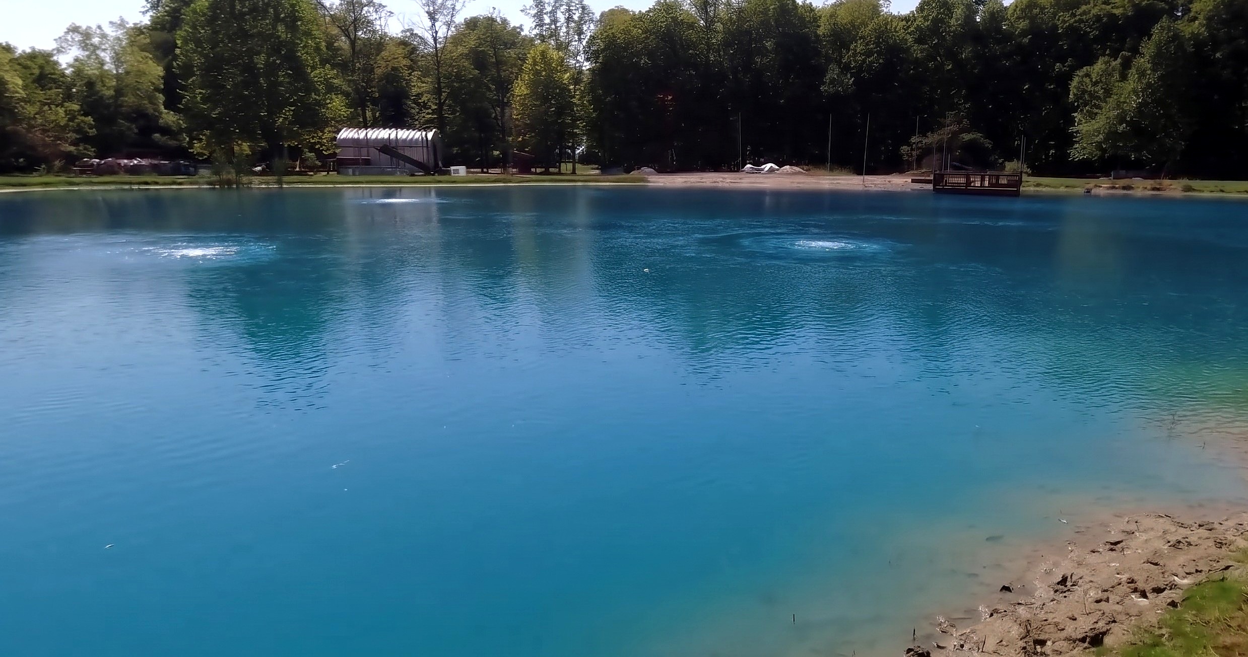
Boat both diffuser sleds 100 ft into deep water and balance the manifold valves.
Parts in this step: (B) Compressor manifold with feeder lines, (C) First fine-bubble diffuser sled, (D) Second fine-bubble diffuser sled
You'll need: Jon boat with electric trolling motor, Pond aeration system, Weighted rubber air hose, Retrieval rope
- 8.1 Motor out and lower the first diffuser into 19 feet of water
- Set the first fine-bubble diffuser sled (C) on the jon boat bow.
- Motor backward to the pond center as a shore helper feeds the 5/8 in hose.
- Lower the first sled upright to the bottom in 19 ft of water by the retrieval rope.
- 8.2 Close the shallow line's manifold valve to force air to the deep diffuser
- Return to shore; all air escapes through the shallow second diffuser at 4 in depth.
- Close the shallow valve on the compressor manifold with feeder lines (B) to force air to the 19 ft head.
- Check for a strong surface boil over the deep diffuser.
- 8.3 Deploy the second diffuser into deep water by boat
- Re-open the second valve on the compressor manifold with feeder lines (B).
- Motor out 100 ft with the second fine-bubble diffuser sled (D), paying out the second hose.
- Lower the second sled to the bottom by its rope and check both deep-water boils run together.
Key measurements
- First diffuser deployment depth: 19 ft to 20 ft of water
- Airline deployment distance: 100 ft from the shoreline cabinet per diffuser
- Tip: Motor in reverse to pull the heavy airline straight off the bow, clear of the propeller.
- Heads up: Check the trolling motor is clamped to a solid transom before pulling heavy hose under load.
Before you move on: Check for two active fine-bubble surface boils with both manifold valves open.
Step 9: Backfill the Trench and Install the Cabinet Cover
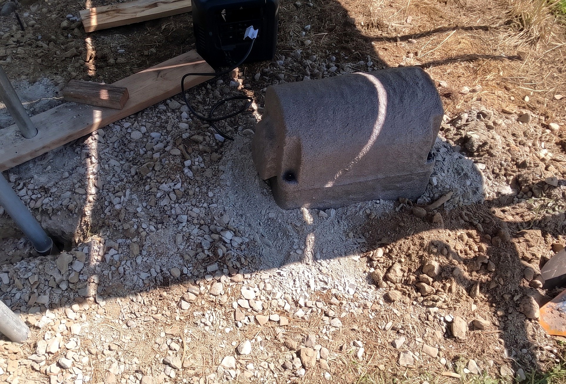
Backfill the conduit trench, tuck hose joints under the cabinet base, and fasten the faux-rock cover.
Parts in this step: (A) Airmax PS20 aerator compressor and base, (B) Compressor manifold with feeder lines, (E) Weatherproof faux-rock cabinet cover
You'll need: Round-point shovel, Portable power station, Pond aeration system, Crushed stone, PVC conduit pipe
- 9.1 Backfill the conduit trench and tuck hose connections under the base
- Shovel soil over both 2 in PVC conduit pipes in the shoreline trench.
- Push the brass barb and hose-clamp connections into the cavity under the Airmax PS20 aerator compressor and base (A).
- Pack crushed stone around the compressor base perimeter.
- 9.2 Secure the faux-rock cover and check wattage draw
- Set and fasten the weatherproof faux-rock cabinet cover (E) over the compressor base.
- Clear crushed stone from the bottom intake sponge filter and side exhaust port.
- Check the portable power station display shows a steady 540 W to 542 W power draw.
Key measurements
- Operating power draw: 540 W to 542 W continuous on both heads
- Tip: Keep gravel off the intake sponge and exhaust vent so the compressor cools.
Finishing
Last Touches
- Have a licensed electrician energize the lakeside panel and plug in the compressor.
- Use small floats or sinking retrieval lines so fishing lures do not snag.
Settle and Startup Schedule
- Gradually ramp up older un-aerated ponds to avoid turning stagnant water at once.
- Run 30 minutes day one; 1, 2, 4, and 8 hours on following days.
Care
- Pull each diffuser sled straight up by its retrieval rope from a boat to clean fouled sticks.
- Periodically check the bottom intake sponge filter under the cabinet cover.
Alternatives
- Mount the cabinet in a powered barn; bury one 1 in airline to a lakeside manifold box.
Commission & test
| Check | What you should see | If not |
|---|---|---|
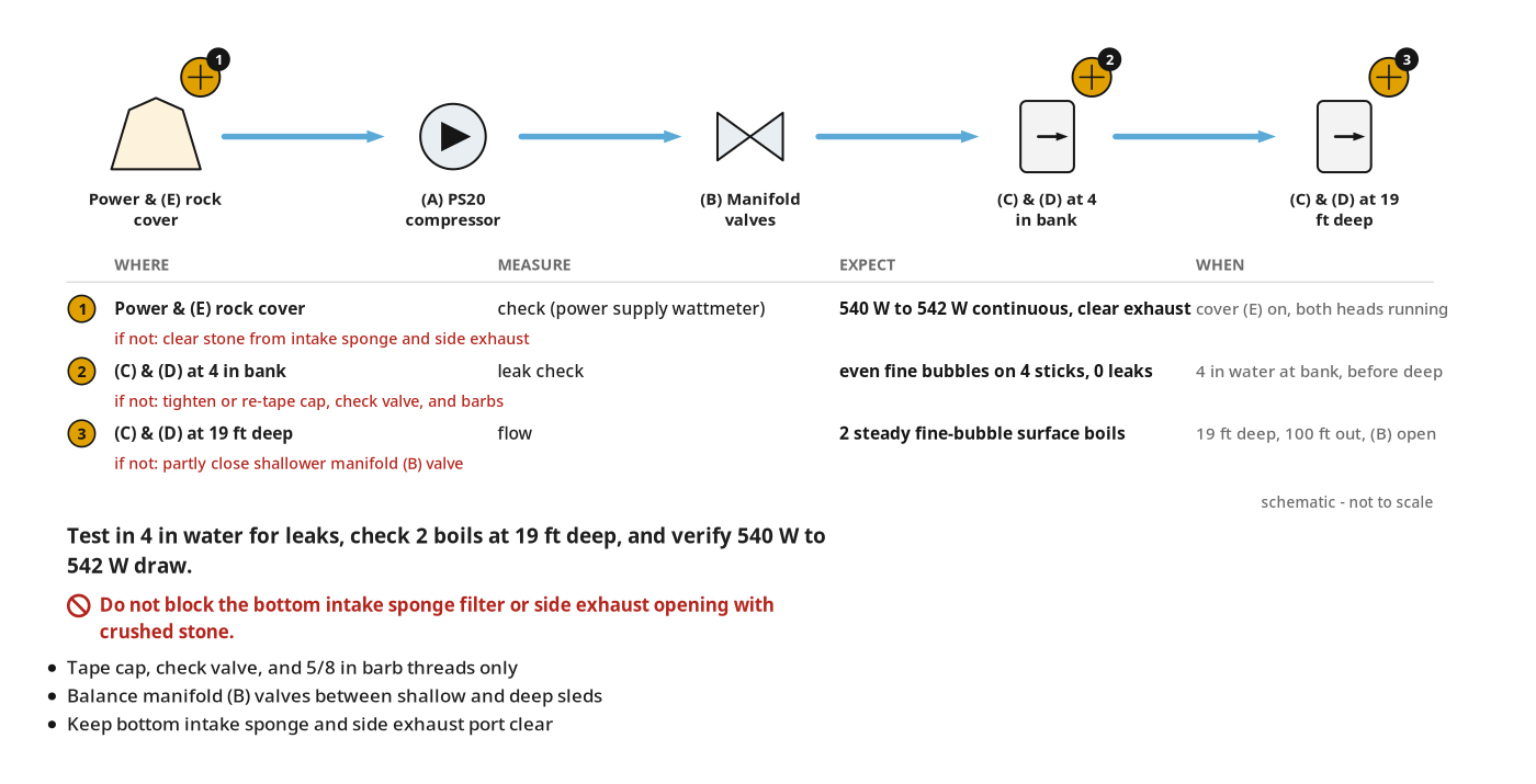
| Submerge each assembled diffuser in 4 in of water by the bank, compressor running. | Microscopic fine bubbles rise evenly across all four diffuser sticks; no joints leak. | Hand-tighten loose fittings or re-tape cap, check valve and barb threads with Teflon tape. |
| Deploy both diffusers in deep water (up to 19 ft); open both cabinet manifold valves. | Two steady fine-bubble boils appear on the surface above the submerged sleds. | Partly close the shallower diffuser's manifold valve to balance backpressure to the deeper head. |
| Check the power supply wattage meter with the faux-rock cover on and both heads running. | Continuous power reads between 540 W and 542 W with clear exhaust port airflow. | Clear crushed stone from the bottom intake sponge filter and side exhaust opening. |
These Specs are built from Indy Farm Life's video “Subsurface Pond Aeration System Installation”. Open the Subsurface Pond Aeration System Installation project page.
