Spetz Specs No. 8682: step-by-step repair guide
Gas Grill Valve Orifice Cleaning and Repair
The complete step-by-step guide made from Indy Farm Life's YouTube video, free on Spetz. For the video, a step-by-step player and answers to your questions, see the Gas Grill Valve Orifice Cleaning and Repair project page.
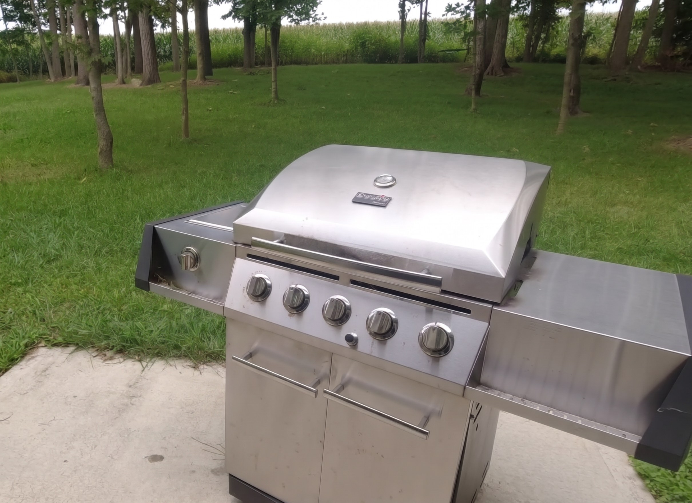
2 steps, 8 parts, 3 tools, 1 materials
Overview
The Fault
- Igniter sparks and gas sounds flowing, yet burners fail to light.
- Vaporized cooking grease builds up, plugging the tiny rear valve orifices.
- Disassembling each burner valve and blasting the orifice with solvent and compressed air restores flow.
Why Fix It Yourself
- A clogged valve orifice mimics a failed gas regulator, avoiding unnecessary regulator replacement.
- Standard parts diagrams show one manifold assembly without detailing internal valve stops.
What It Takes
- Use a Phillips screwdriver, cordless drill/driver, aerosol degreaser, and air compressor.
- No replacement parts needed: clean the five existing brass and metal valves.
What Decides Success
- Keep one valve assembled as a visual reference so internal locking stops align.
- Seat each saddle valve inlet over its manifold crossover tube feed hole.
The fault at a glance
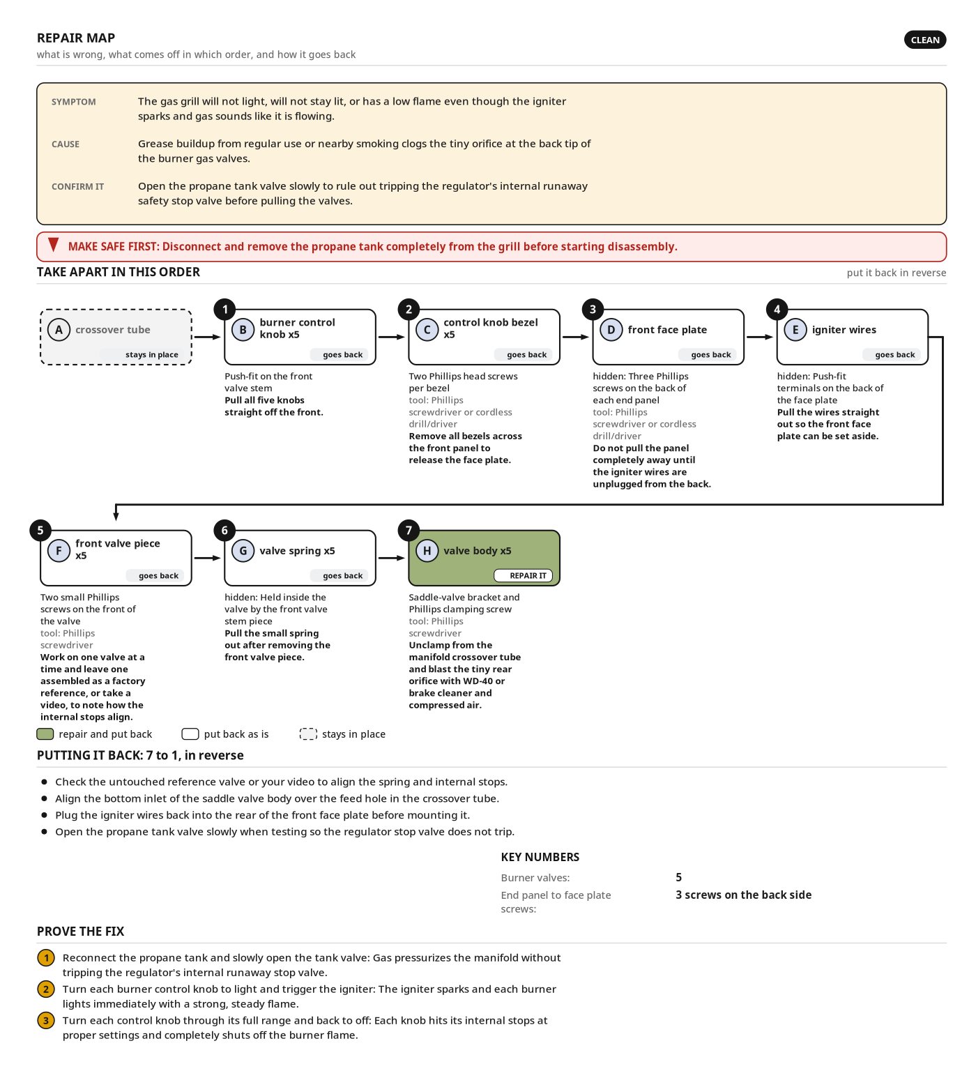
- What you see: The gas grill will not light, will not stay lit, or has a low flame even though the igniter sparks and gas sounds like it is flowing.
- What is wrong: Grease buildup from regular use or nearby smoking clogs the tiny orifice at the back tip of the burner gas valves.
- Confirm it: Open the propane tank valve slowly to rule out tripping the regulator's internal runaway safety stop valve before pulling the valves.
- Burner valves: 5
- End panel to face plate screws: 3 screws on the back side
Make safe first
- Disconnect and remove the propane tank completely from the grill before starting disassembly.
Health and safety
Propane and Gas Valve Safety
- Shut off, disconnect, and completely remove the propane tank from the grill before loosening the control panel or any gas valves.
- Work outdoors away from flames or sparks so residual gas trapped inside the manifold and valves dissipates safely.
- Ensure all cleaned solvent evaporates and check reassembled gas valves for leaks before reconnecting the propane tank and lighting the burners.
Aerosol Solvents and Cleaners
- Wear chemical-resistant gloves and eye protective equipment when handling WD-40, brake cleaner, Easy Off, Zep, or Break-Up cleaners.
- Spray brake cleaner and aerosol degreasers outdoors in fresh air to avoid breathing hazardous solvent vapors and caustic mists.
- Keep flammable aerosol solvents and freshly sprayed valve parts away from sparks, open flames, and heat until completely dry.
Compressed Air and Orifice Blowback
- Wear tight-fitting eye protective equipment whenever spraying compressed air or pressurized aerosol solvent through the tiny gas valve orifices.
- Aim the valve orifice away from your face and body to prevent blowback of pressurized solvent and dissolved grease.
- Never point the air compressor blow nozzle at your skin, as compressed air can drive solvent and debris into tissue.
Sheet Metal, Wiring, and Tools
- Unplug the rear igniter wires before pulling the front face plate away so the panel does not recoil or damage wiring.
- Wear cut-resistant gloves when removing the metal front control panel and reaching inside the grill housing around sharp sheet-metal edges.
- Keep your free hand clear of the spinning Phillips bit when removing control panel screws with the 20V cordless drill/driver.
Diagnose & make safe
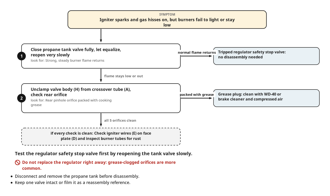
- Check the symptom: igniter sparks and gas hisses on, but burners fail to light or stay low.
- Test the regulator safety valve first: fully close the propane tank, then reopen the valve slowly.
- Do not replace the gas regulator right away; grease-clogged valve orifices are much more common.
- Disconnect and remove the propane tank from the grill before disassembly.
- Film one valve before disassembly, or keep one intact as a reassembly reference.
Tools
- Phillips screwdriver (hand screwdriver, Phillips head)
- Cordless drill/driver (power drill/driver, DeWalt, XR, 20V Max, 4Ah battery, Phillips bit) (optional)
- Air compressor with blow nozzle (air compressor) (optional)
Materials
- WD-40 or brake cleaner (1 can, aerosol degreaser / solvent, WD-40)
Hardware
| Hardware | Size | Count | Used in steps |
|---|---|---|---|
| Phillips screw | 10 | 1 | |
| Phillips mounting screw | 6 | 1 | |
| Small Phillips screw | 2 | 2 | |
| Phillips clamping screw | 1 | 2 |
Finishes & supplies, in the order they go on
| Product | What it does | Mix & coats | Dry time | Applied with |
|---|---|---|---|---|
| WD-40 or brake cleaner | Dissolve grease clogging the internal valve body and tiny rear orifice | Aerosol spray straw followed by an air compressor with blow nozzle |
Parts
| Part | Name | Qty | Size | Notes |
|---|---|---|---|---|
| A | crossover tube | x1 | Manifold tube with feed holes that supply gas into the bottom of each saddle-style burner valve. | |
| B | burner control knob | x5 | 5 · Pulls straight off the front valve stem. | |
| C | control knob bezel | x5 | 5 · Mounted under each control knob with Phillips head screws; must come off to free the front face plate. | |
| D | front face plate | x1 | Secured by three screws on the back side where the end panels meet the face. | |
| E | igniter wires | count yours | Attached to the back of the front face plate; pull out to detach before setting the panel aside. | |
| F | front valve piece | x5 | 5 · Turns the valve and has internal stops to lock the knob positions; keep one valve intact as a reference. | |
| G | valve spring | x5 | 5 · Small internal spring located behind the front valve piece. | |
| H | valve body | x5 | 5 · Clamps onto the crossover tube like a saddle valve; clear grease from the tiny orifice at the rear tip. |
Before you start
Step by step
Step 1: Remove the Control Knobs and Front Face Plate
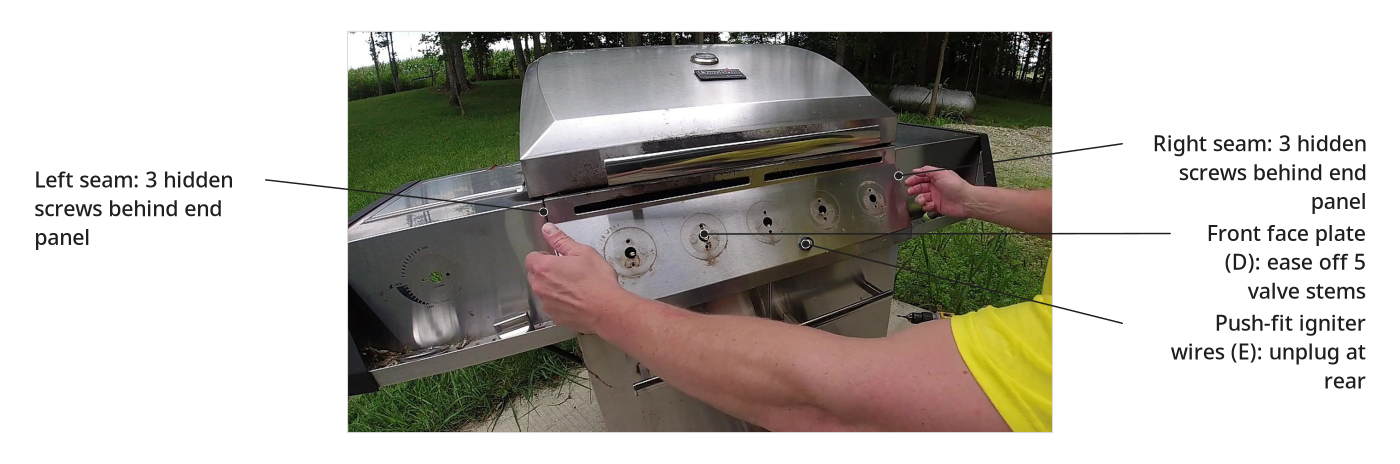
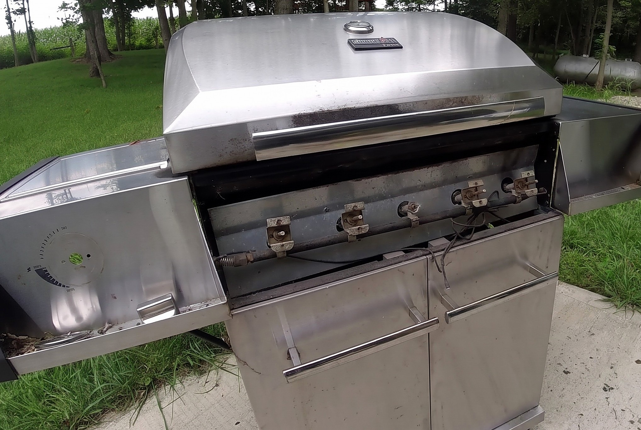
Five burner control knobs, knob bezels, and front face plate removed with igniter wires unplugged, exposing the internal gas manifold.
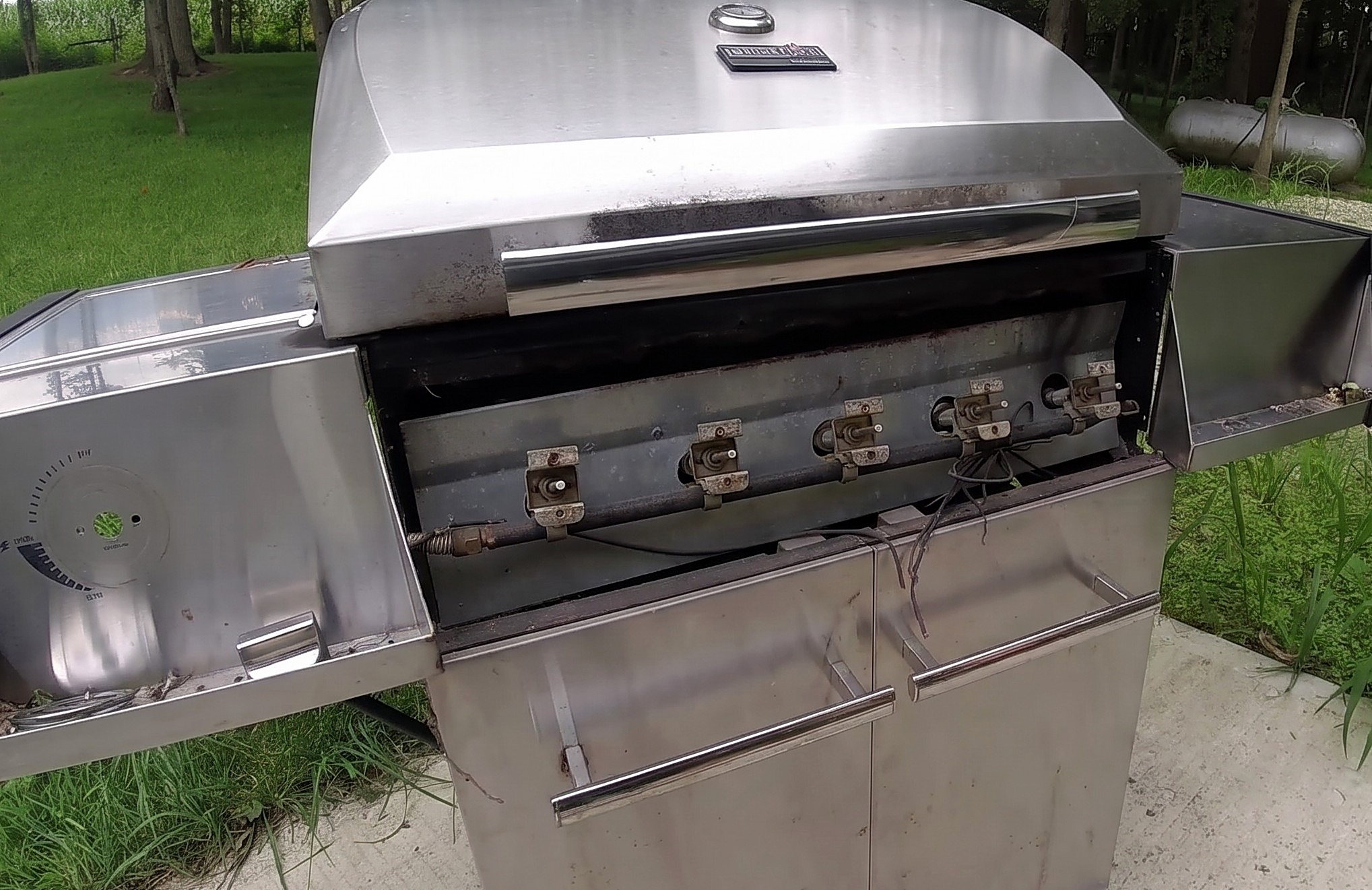
Parts in this step: (B) burner control knob, (C) control knob bezel, (D) front face plate, (E) igniter wires
You'll need: Phillips screwdriver, Cordless drill/driver, Phillips screw, Phillips mounting screw
- 1.1 Pull off the burner control knobs
- Pull all five burner control knobs (B) straight off the front valve stems by hand.
- Set all five knobs aside for reassembly.
- 1.2 Unscrew and remove the knob bezels
- Unscrew both Phillips screws in each control knob bezel (C) with a Phillips screwdriver.
- Back out all ten bezel screws with a cordless drill/driver and Phillips bit.
- Lift all five bezels off the front face plate (D) and save the screws.
- 1.3 Remove the face plate and disconnect igniter wires
- Find the three Phillips mounting screws behind each end panel.
- Unscrew all six rear end-panel screws holding the front face plate.
- Ease the front face plate forward off the five valve stems without yanking wires.
- Unplug the push-fit igniter wires (E) from the panel back and set it aside.
Key measurements
- Control knob bezels: 5 bezels across the front panel, 2 Phillips screws each
- End panel mounting screws: 3 Phillips screws behind each end panel
- Tip: Find the rear mounting screws behind the side shelves where end panels meet the front face plate.
- Tip: Switch from hand screwdriver to cordless drill/driver to remove the sixteen front and rear panel screws faster.
- Heads up: Do not pull the front face plate fully off the grill until the rear igniter wires are unplugged.
Before you move on: Five bezels and six rear end-panel screws are out; igniter wires are unplugged intact from the front face plate.
Step 2: Remove the Gas Valve and Inspect the Orifice
Each burner valve body is unclamped from the crossover tube, its rear pinhole orifice cleared of grease with solvent and compressed air, and the valve reattached.
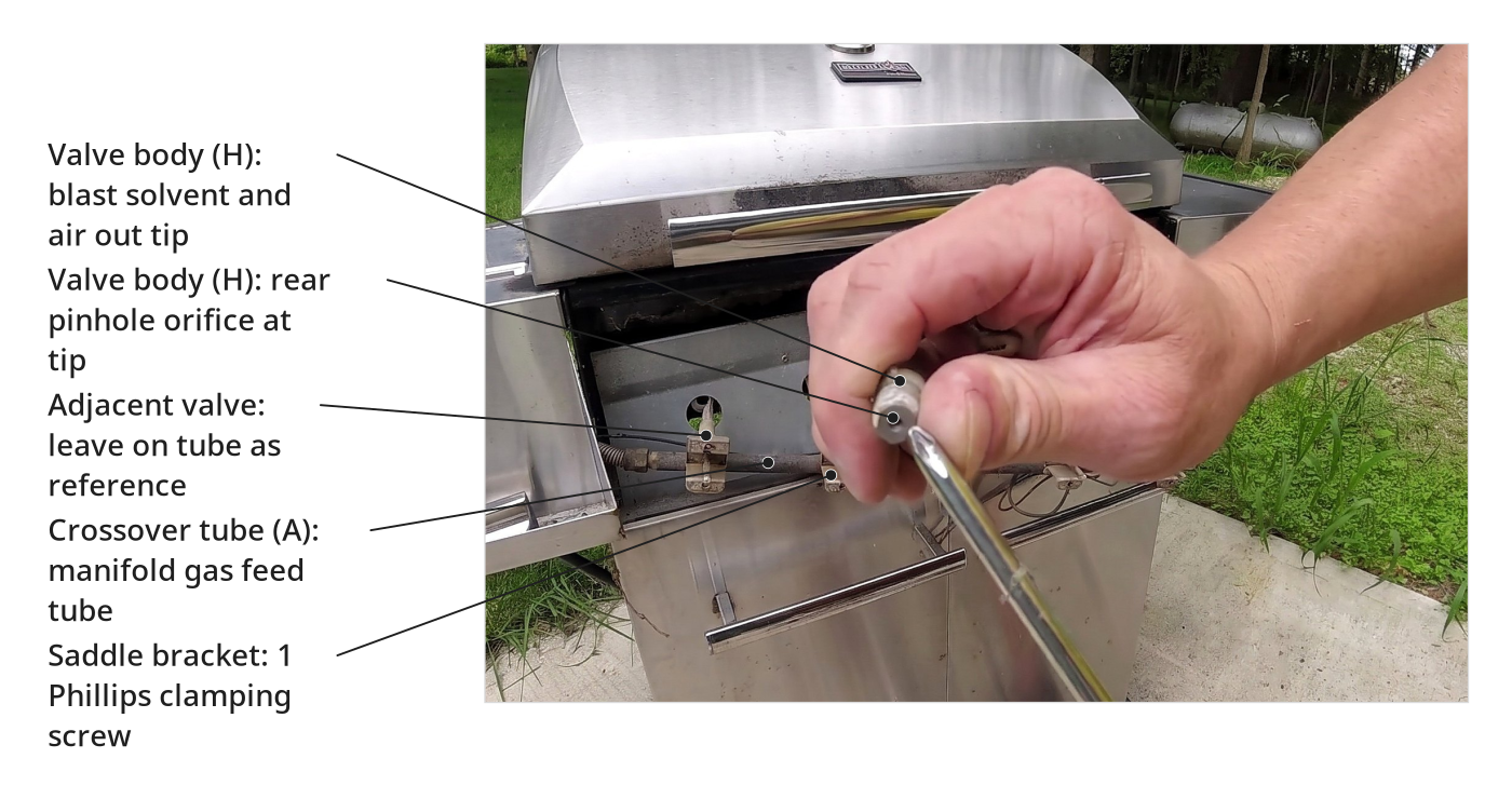
Parts in this step: (A) crossover tube, (F) front valve piece, (G) valve spring, (H) valve body
You'll need: Phillips screwdriver, Air compressor with blow nozzle, WD-40 or brake cleaner, Small Phillips screw, Phillips clamping screw
- 2.1 Remove the front valve stem cap and spring
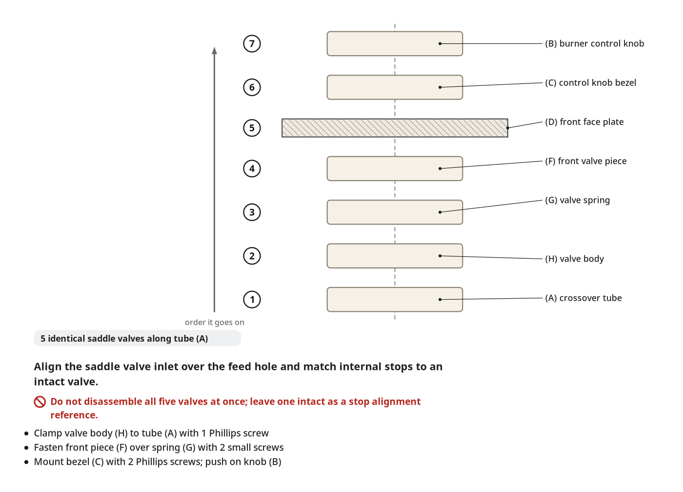
- Leave at least one burner valve untouched as an internal stop alignment reference.
- Unscrew the two small Phillips screws holding front valve piece (F) to valve body (H).
- Pull off the front valve piece, noting how its internal locking stops orient.
- Remove the small valve spring (G) from inside the valve front.
- 2.2 Unclamp the saddle valve body from the crossover tube
- Pull manifold crossover tube (A) slightly forward for screwdriver access.
- Unscrew the Phillips clamping screw on the crossover tube's saddle bracket.
- Detach the rear valve body from the crossover tube's bottom gas feed hole.
- 2.3 Inspect the orifice at the tip of the valve
- Check the tiny pinhole orifice at the valve body's rear tip for grease blockages.
- Spray WD-40 or brake cleaner into the valve body and orifice to dissolve packed grease.
- With an air compressor blow nozzle in the valve body, blast air out the rear orifice.
- Clamp the cleaned valve body back over its crossover tube feed hole.
- Reinstall the valve spring and front valve piece matching the untouched reference valve; repeat on remaining valves.
Key measurements
- Burner valves: 5 identical saddle-style valves on the crossover tube
- Front valve piece fasteners: 2 small Phillips screws per valve
- Saddle bracket fastener: 1 Phillips clamping screw per valve
- Tip: Service one valve at a time; pop open an adjacent factory-assembled valve to check spring and stop alignment if needed.
- Tip: Carburetor cleaner or heavy-duty grill degreaser can replace WD-40 or brake cleaner for stubborn grease.
- Heads up: Wear eye protective equipment when spraying aerosol solvent and compressed air through small valve passages.
Before you move on: Air flows freely through every rear pinhole orifice, each saddle valve inlet aligns over its crossover tube feed hole, and internal stops match the reference valve.
Finishing
Last Touches
- Plug the igniter wires into the front face plate's rear terminals.
- Slide the front face plate over the valve stems; fasten the six rear end-panel screws.
- Screw five control knob bezels onto the face plate; press five knobs onto the stems.
Care
- Clean burner valve orifices periodically as routine maintenance to keep flames strong.
- Open the propane tank valve slowly every time you grill so the regulator stop valve never trips.
Alternatives
- Pull internal burner tubes from the firebox; spray carburetor or brake cleaner into the rear valve orifices.
- Replace rusted internal burner tubes while the grill is open if flames stay uneven after valve cleaning.
Prove the fix
| Check | What you should see | If not |
|---|---|---|
| Reconnect the propane tank and slowly open the tank valve. | Gas pressurizes the manifold without tripping the regulator's internal runaway stop valve. | Fully close the propane tank valve, let pressure equalize, and reopen very slowly. |
| Turn each burner control knob to light and trigger the igniter. | The igniter sparks and each burner lights immediately with a strong, steady flame. | Check igniter wires are plugged into the face plate back, or re-clean the valve orifice with solvent and compressed air. |
| Turn each control knob through its full range and back to off. | Each knob hits its internal stops at proper settings and completely shuts off the burner flame. | Remove the knob and front valve piece; realign the internal locking stops and spring against an untouched valve. |
These Specs are built from Indy Farm Life's video “Gas Grill Valve Orifice Cleaning and Repair”. Open the Gas Grill Valve Orifice Cleaning and Repair project page.
