Spetz Specs No. 7437: step-by-step system install guide
Truck Bed LED Lights Wired with a Dome Light Relay
The complete step-by-step guide made from Indy Farm Life's YouTube video, free on Spetz. For the video, a step-by-step player and answers to your questions, see the Truck Bed LED Lights Wired with a Dome Light Relay project page.
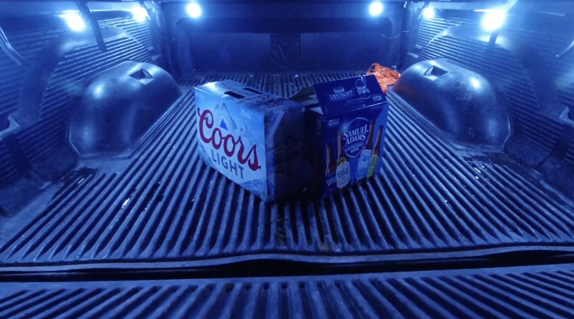
5 steps, 4 parts, 2 tools, 11 materials
Overview
The System
- Powers a 12 V truck bed LED light strand (8 squares, 6 LEDs per square) from the battery.
- Auto-switches power via a 5-pin automotive relay triggered by the cab dome light circuit.
Why Do It Yourself
- Tailgate pin switches leave bed lights on when hauling plywood or lumber with the tailgate down.
- Manual switches without a timer risk draining the battery if forgotten.
- Tapping the dome light turns bed lights on with any door or the cab dial.
- Uses the built-in 15-minute dome light shutoff timer to prevent dead batteries.
What It Takes
- Needs a wire crimper and cutter, 12 V wire stripping, and reading a 5-pin relay diagram.
- Find the factory dome light wire under the cab step plate or near the emergency brake.
- Route split wire loom under the truck frame and fish wire up the rear bed sidewall.
What Decides Success
- Connect the LED positive lead to relay terminal 87, not terminal 87a.
- Install a 10 A or 15 A inline fuse at the battery and shelter splices from weather.
The system at a glance
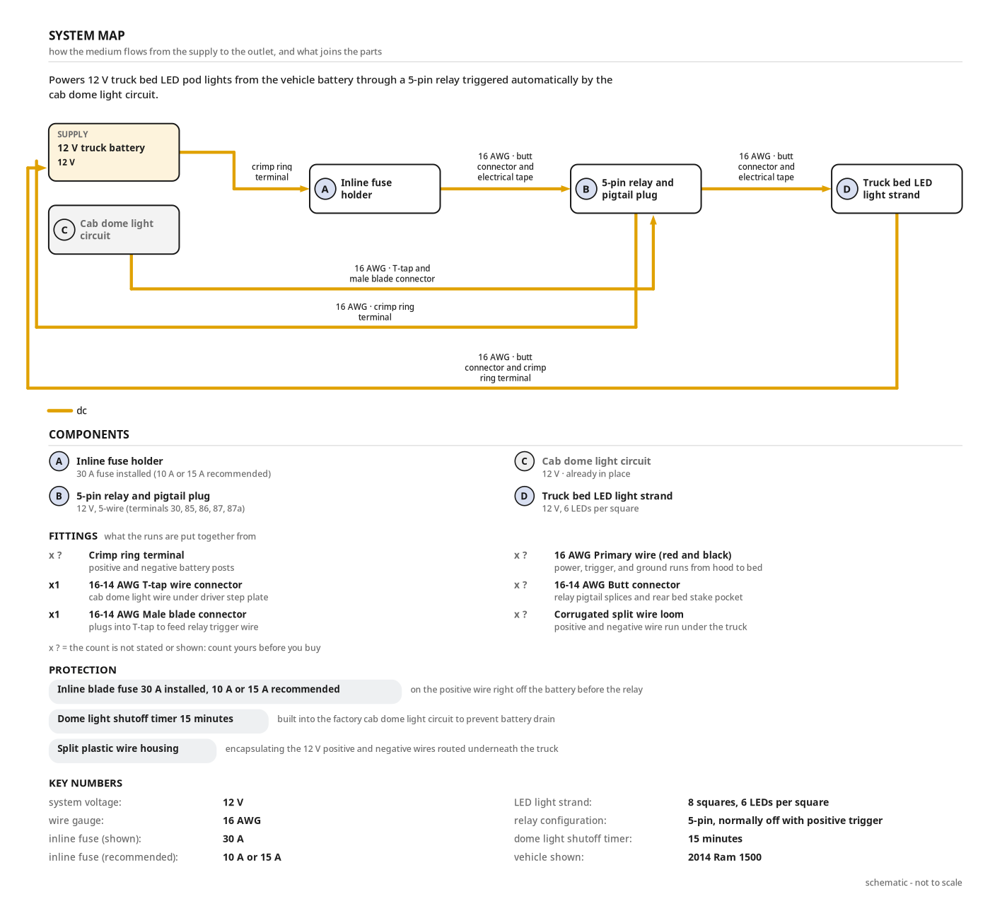
- Powers 12 V truck bed LED pod lights from the vehicle battery through a 5-pin relay triggered automatically by the cab dome light circuit.
- Supply: 12 V truck battery, 12 V
- supply → Inline fuse holder: dc, wire, crimp ring terminal
- Inline fuse holder → 5-pin relay and pigtail plug: dc, wire, 16 AWG, butt connector and electrical tape
- Cab dome light circuit → 5-pin relay and pigtail plug: dc, wire, 16 AWG, T-tap and male blade connector
- 5-pin relay and pigtail plug → supply: dc, wire, 16 AWG, crimp ring terminal
- 5-pin relay and pigtail plug → Truck bed LED light strand: dc, wire, 16 AWG, butt connector and electrical tape
- Truck bed LED light strand → supply: dc, wire, 16 AWG, butt connector and crimp ring terminal
- Protection: Inline blade fuse, 30 A installed, 10 A or 15 A recommended, on the positive wire right off the battery before the relay
- Protection: Dome light shutoff timer, 15 minutes, built into the factory cab dome light circuit to prevent battery drain
- Protection: Split plastic wire housing, encapsulating the 12 V positive and negative wires routed underneath the truck
- system voltage: 12 V
- wire gauge: 16 AWG
- inline fuse (shown): 30 A
- inline fuse (recommended): 10 A or 15 A
- LED light strand: 8 squares, 6 LEDs per square
- relay configuration: 5-pin, normally off with positive trigger
- dome light shutoff timer: 15 minutes
- vehicle shown: 2014 Ram 1500
Health and safety
Battery and Fuse Safety
- Disconnect the negative battery terminal before attaching crimp ring terminals to prevent accidental arcs and short circuits.
- Install a 10A or 15A inline blade fuse on the positive lead close to the battery to prevent electrical fires.
- Keep metal tools clear of the positive battery terminal so they cannot bridge to bare metal under the hood.
Relay and Tap Wiring
- Cap the unused 87a center relay wire with electrical tape so the live lead cannot short against bare metal.
- Check the factory dome light wire color before clamping the T-tap so you do not pierce a critical vehicle circuit.
- Insulate all wire splices with butt connectors and electrical tape to prevent shorts inside the cab and engine bay.
Soldering and Cutting Tools
- Keep the hot soldering iron away from skin, plastic split wire loom, and battery gases while soldering connections.
- Solder only in an open, ventilated area so you do not inhale fumes from heated solder and wire insulation.
- Keep fingers out of the jaws when using the wire crimper and cutter on 16-gauge wire and zip ties.
Underbody Routing Hazards
- Let the exhaust system cool completely and secure the parked truck before crawling underneath the frame to route wires.
- Enclose the positive and negative underbody wires in corrugated split wire loom to protect against abrasion and shorting.
- Secure the split wire loom high on the frame with zip ties, clear of moving parts, hot exhaust, and debris.
Checks before you start
- Check the vehicle has a 12 V battery and a cab dome light circuit with a 15-minute shutoff timer.
- Use a 10 A or 15 A blade fuse in the inline fuse holder (A), not an oversized 30 A fuse.
- Use 16 AWG stranded red and black primary wire with 16-14 AWG T-tap, male blade, and butt connectors.
- Look up the factory dome light wire color and harness location for your truck year and model first.
- Check the terminal numbers stamped in the relay base; pigtail wire colors vary by brand.
- Keep the inline fuse out or positive battery ring disconnected until all splices are insulated.
Tools
- Wire Crimper and Cutter (hand wire crimping and cutting tool)
- Soldering Iron (electric soldering iron) (optional)
Materials
- LED Truck Bed Light Strand (1 strand (8 pods), 12V LED pod light strand, 6 LEDs per square, 8 squares per strand)
- 5-Pin Automotive Relay with Pigtail Harness (1, 5-pin SPDT automotive relay with socket pigtail, 5-wire harness (terminals 30, 85, 86, 87, 87a))
- Electrical Wire (2 rolls, low-voltage stranded primary wire, 16-gauge, black and red)
- Electrical Tape (1 roll, vinyl electrical tape, black)
- Butt Connectors (insulated crimp butt splice connectors)
- Male Blade Connectors (1, insulated male spade terminal disconnects, 16-14 AWG, blue)
- T-Tap Wire Connector (1, self-stripping quick-splice T-tap connector, 16-14 AWG)
- Inline Blade Fuse Holder with Fuse (1, inline automotive blade fuse holder, 10A or 15A blade fuse recommended (30A shown))
- Crimp Ring Terminals (insulated ring terminal connectors)
- Corrugated Split Wire Loom (split plastic wire conduit)
- Zip Ties (nylon cable ties)
Hardware
| Hardware | Size | Count | Used in steps |
|---|---|---|---|
| Crimp Ring Terminals | 3 | 3 | |
| Butt Connectors | 6 | 3, 4, 5 | |
| 16-14 AWG T-Tap Wire Connector | 1 | 4 | |
| 16-14 AWG, blue Male Blade Connectors | 1 | 4 | |
| Zip Ties | 5 |
Finishes & supplies, in the order they go on
| Product | What it does | Mix & coats | Dry time | Applied with |
|---|---|---|---|---|
| Electrical Tape | Cap unused 87a relay lead; insulate crimp butt connector splices. | Hand-wrapped tightly over connectors and wire ends | ||
| Corrugated Split Wire Loom | Enclose and protect 12 V positive and negative wires under the truck. | Slipped over the 16 AWG wire pair and secured with zip ties |
Components
| Part | Name | Qty | Size | Notes |
|---|---|---|---|---|
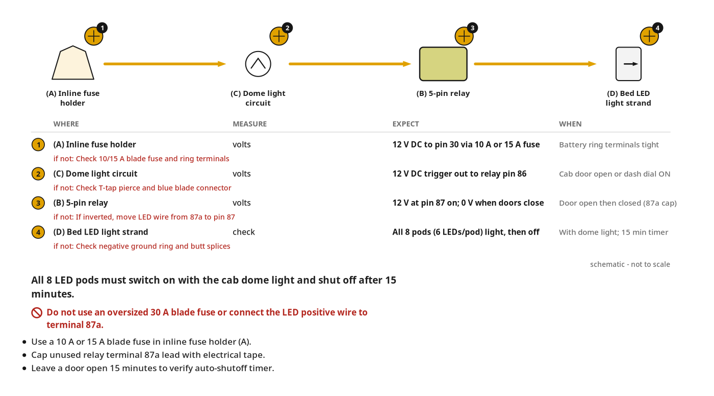
| A | Inline fuse holder | x1 | 30 A fuse installed (10 A or 15 A recommended) | Cut the wire loop in half; wire between the positive battery post and relay terminal 30. |
| B | 5-pin relay and pigtail plug | x1 | 12 V, 5-wire (terminals 30, 85, 86, 87, 87a) | Mounted under the hood; cap the center 87a lead with electrical tape and leave it disconnected. |
| C | Cab dome light circuit | x1 | 12 V | Factory dome light wire located in the harness under the driver-side step plate or near the e-brake. |
| D | Truck bed LED light strand | x1 | 12 V, 6 LEDs per square | 1 strand (8 squares) · Mounted under the bed rails around the interior perimeter of the pickup bed. |
Step by step
Step 1: Identify the Relay Terminals and Harness Wires
Separate the 5-pin relay and pigtail plug (B) and identify each numbered terminal wire.
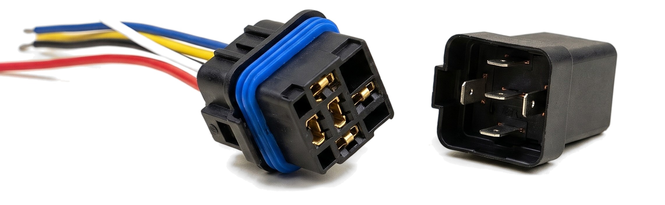
Parts in this step: (B) 5-pin relay and pigtail plug
You'll need: 5-Pin Automotive Relay with Pigtail Harness
- 1.1 Separate the relay from the pigtail socket
- Unplug the 5-pin relay and pigtail plug (B) to expose the five metal blades and socket slots.
- Find the terminal numbers stamped in the relay base: 30, 85, 86, 87, and 87a.
- Align the keyed pigtail socket and relay pins; they only fit one way.
- 1.2 Identify each wire on the 5-pin relay harness
- Leave the center wire on terminal 87a (yellow or red, by harness) unused.
- Note terminal 30 (red wire): constant 12 V positive input from the battery.
- Note terminal 85 (black wire): negative ground return to the battery.
- Note terminal 87 (blue wire): switched 12 V positive output to the bed lights.
- Note terminal 86 (white wire): 12 V positive trigger input from the dome light.
Key measurements
- Relay rating: 12 V DC, 5 terminals (30, 85, 86, 87, 87a)
- Tip: Check terminal numbers stamped on the relay base, not wire colors alone; harness colors vary by maker.
- Heads up: Do not confuse voltage with amperage: both circuits use 12 V; the relay lets a low-amperage trigger switch a higher-amperage load.
Before you move on: Check all five pigtail wires match terminals 30, 85, 86, 87, and 87a on the relay base.
Step 2: Map Out the Relay and Dome Light Wiring Circuit
Map the normally-off positive-trigger circuit and prep the inline fuse holder (A).
Parts in this step: (A) Inline fuse holder, (B) 5-pin relay and pigtail plug, (C) Cab dome light circuit, (D) Truck bed LED light strand
You'll need: Wire Crimper and Cutter, Inline Blade Fuse Holder with Fuse, 5-Pin Automotive Relay with Pigtail Harness, LED Truck Bed Light Strand
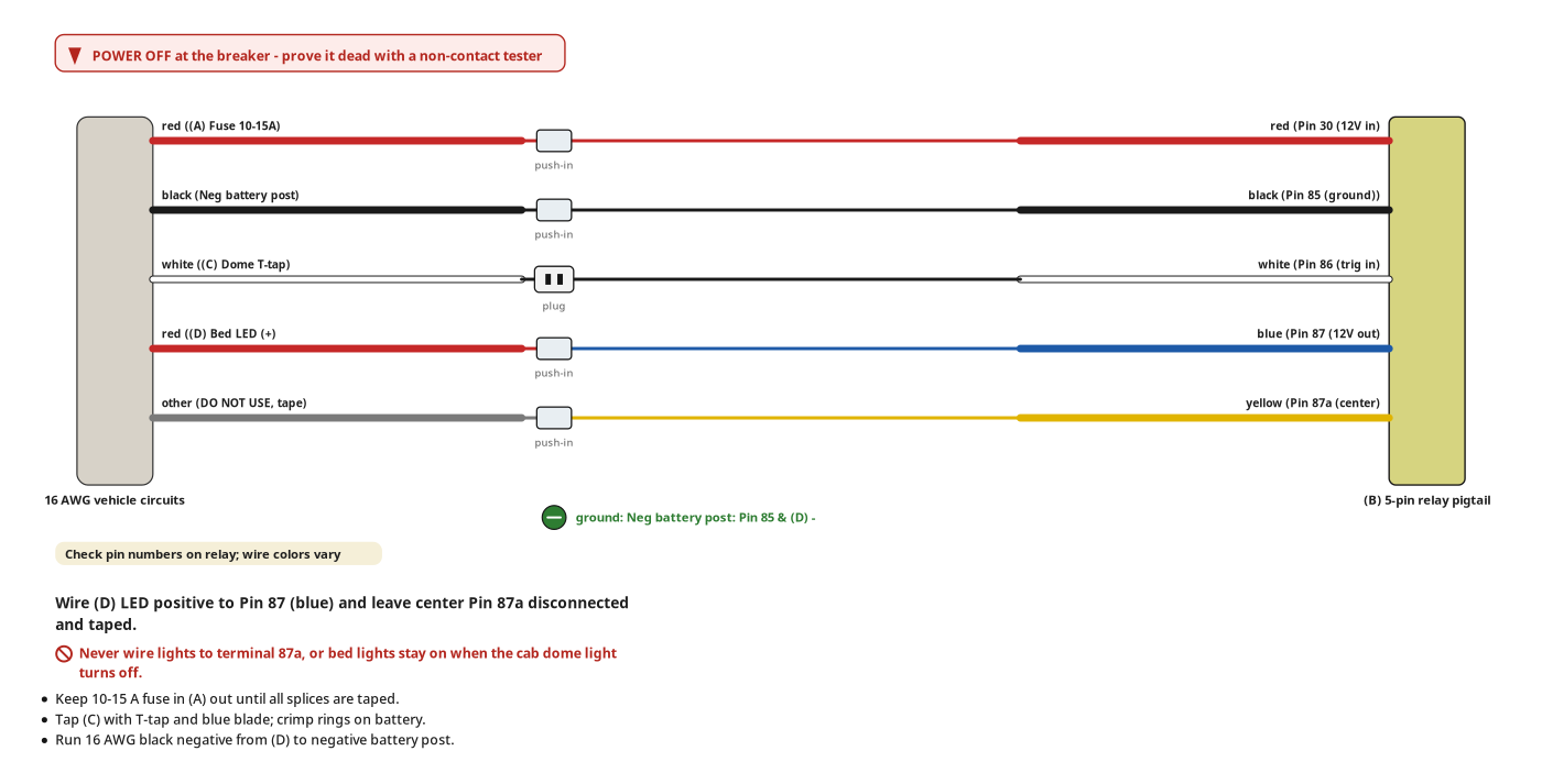
- 2.1 Map the battery, inline fuse, and relay ground connections
- Cut the inline fuse holder (A) wire loop in half with the wire cutter.
- Assign one fuse holder lead to the positive battery post, the other to terminal 30 on the 5-pin relay and pigtail plug (B).
- Plan relay terminal 85 ground wire (black) to the negative battery post.
- 2.2 Map the dome light trigger and LED light output circuit
- Plan the cab dome light circuit (C) trigger wire to relay terminal 86 (white wire).
- Plan the relay terminal 87 (blue wire) switched 12 V output to the truck bed LED light strand (D) positive lead.
- Plan the LED light strand negative ground lead to the negative battery post.
- 2.3 Verify the normally-off positive-trigger diagram and isolate terminal 87a
- Match the Normally OFF Relay with a POSITIVE Trigger schematic on the relay instruction sheet.
- Leave center terminal 87a disconnected to power the bed only when the dome light is hot.
- Never wire lights to terminal 87a; it inverts the circuit, keeping bed lights on with the dome light off.
Key measurements
- Inline blade fuse rating: 10 A or 15 A (step down from 30 A).
- Circuit wire gauge: 16 AWG stranded red and black
- Tip: Replace the 30 A inline fuse, which is oversized for LED lights, with a 10 A or 15 A blade fuse.
- Heads up: Wiring LED positive to terminal 87a instead of terminal 87 inverts operation, keeping bed lights on when the dome light is off.
Before you move on: Check LED positive output goes to terminal 87 and terminal 87a is unconnected.
Step 3: Wire the Inline Fuse and Relay to the Battery
Inline fuse holder (A) and 5-pin relay and pigtail plug (B) wired to the battery with terminal 87a capped.
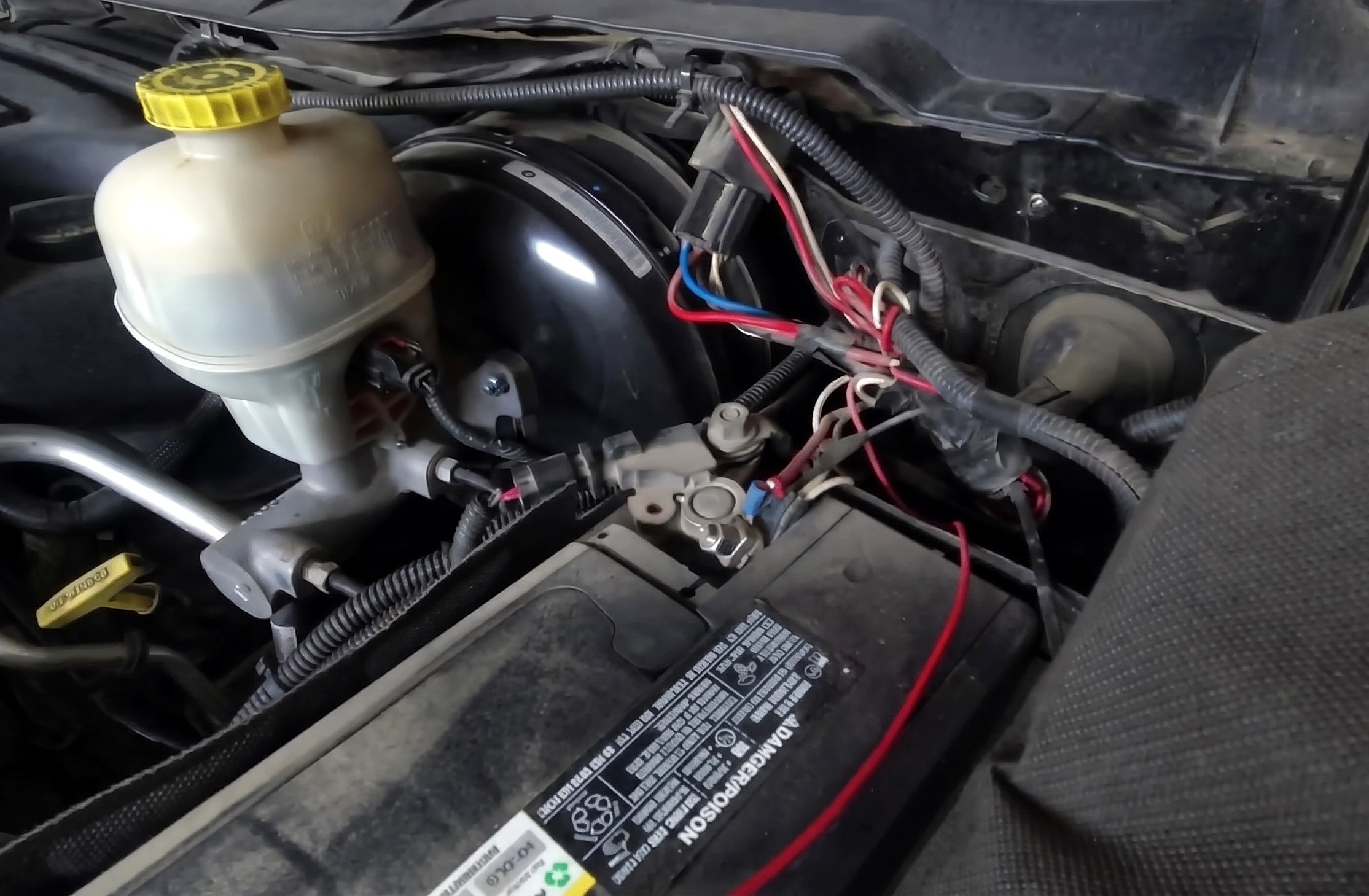
Parts in this step: (A) Inline fuse holder, (B) 5-pin relay and pigtail plug
You'll need: Wire Crimper and Cutter, Soldering Iron, Inline Blade Fuse Holder with Fuse, 5-Pin Automotive Relay with Pigtail Harness, Electrical Wire, Butt Connectors, Crimp Ring Terminals, Electrical Tape
- 3.1 Connect the inline fuse holder and relay to the positive battery post
- Crimp a ring terminal to the inline fuse holder (A) input lead and attach to the positive battery post.
- Splice the fuse holder output to terminal 30 on the 5-pin relay and pigtail plug (B) with a butt connector.
- Wrap the butt splice with electrical tape and place the relay under the hood.
- 3.2 Cap the unused 87a wire and land the ground wires on the battery
- Cap the cut end of the unused terminal 87a center wire tightly with electrical tape.
- Splice 16 AWG black wire to the relay terminal 85 ground wire with a butt connector.
- Crimp ring terminals onto the relay ground and bed light negative return wires; attach both to the negative battery post.
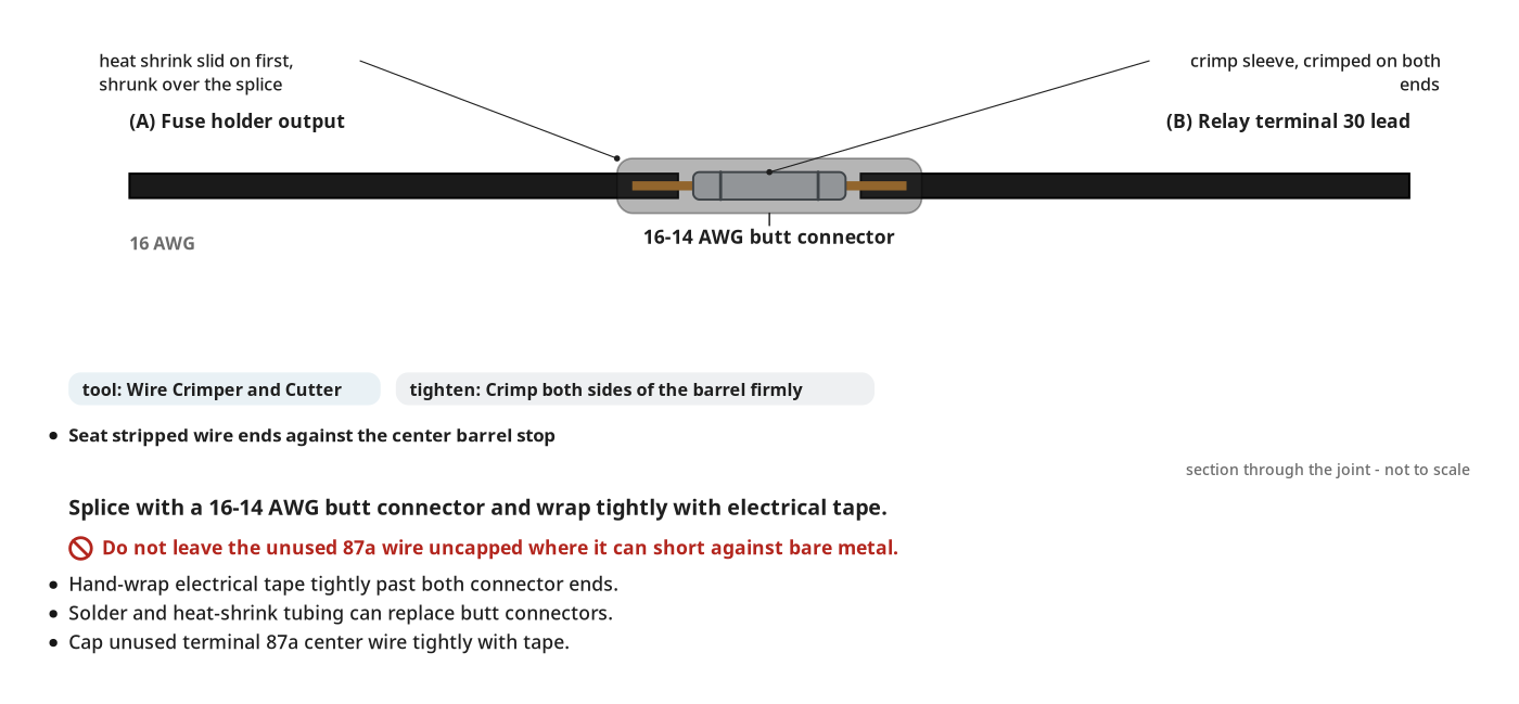
Key measurements
- Supply voltage: 12 V DC at the truck battery
- Ground wire size: 16 AWG black primary wire
- Tip: Solder and heat-shrink tubing can replace crimp butt connectors and electrical tape on splices.
- Heads up: Cap the unused 87a center wire with electrical tape so the live lead cannot short against bare metal under the hood.
Before you move on: Check the inline fuse sits between the positive battery post and terminal 30, with unused lead 87a taped shut.
Step 4: Tap the Dome Light Wire and Route the Trigger Lead
Tap the cab dome light circuit (C) and route it through the firewall to relay trigger terminal 86.
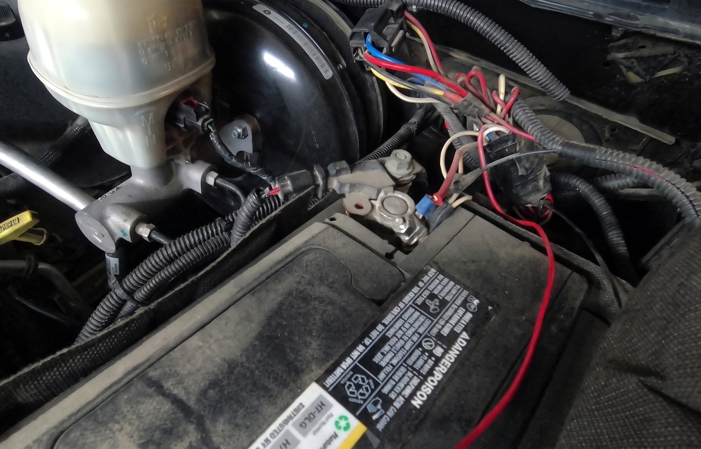
Parts in this step: (B) 5-pin relay and pigtail plug, (C) Cab dome light circuit
You'll need: Wire Crimper and Cutter, T-Tap Wire Connector, Male Blade Connectors, Electrical Wire, Butt Connectors, Electrical Tape, 5-Pin Automotive Relay with Pigtail Harness
- 4.1 Identify the dome light wire for your truck model
- Find the cab dome light circuit (C) wire color for your truck year and model on owner forum wiring diagrams.
- Find the wire under the driver-side door step plate or high on the harness near the emergency brake.
- If the floor harness wire color is unclear, trace the wire at the cab dome light assembly.
- 4.2 Clamp the T-tap onto the dome light wire and route through the firewall
- Squeeze the 16-14 AWG T-tap connector shut around the dome light wire until the metal blade pierces the insulation.
- Crimp a blue 16-14 AWG male blade connector onto the 16 AWG trigger wire and plug it into the T-tap.
- Route the trigger wire out through an existing firewall hole; do not drill a new opening.
- Splice the trigger wire to terminal 86 (white wire) on 5-pin relay and pigtail plug (B) with a butt connector and electrical tape.
Key measurements
- T-tap and male blade connector rating: 16-14 AWG
- Trigger wire gauge: 16 AWG
- Harness location (2014 Ram 1500): under driver-side step plate or near e-brake.
- Tip: Route the trigger wire through an existing firewall opening instead of poking a new hole.
- Heads up: Check the dome light wire color before clamping the T-tap so you do not pierce another circuit.
Before you move on: Tug the male blade connector to check it is locked into the T-tap and routed cleanly through the firewall.
Step 5: Route the Power Wires to the Truck Bed Lights
12 V power and ground wires run in split loom under the truck and splice to the truck bed LED light strand (D).
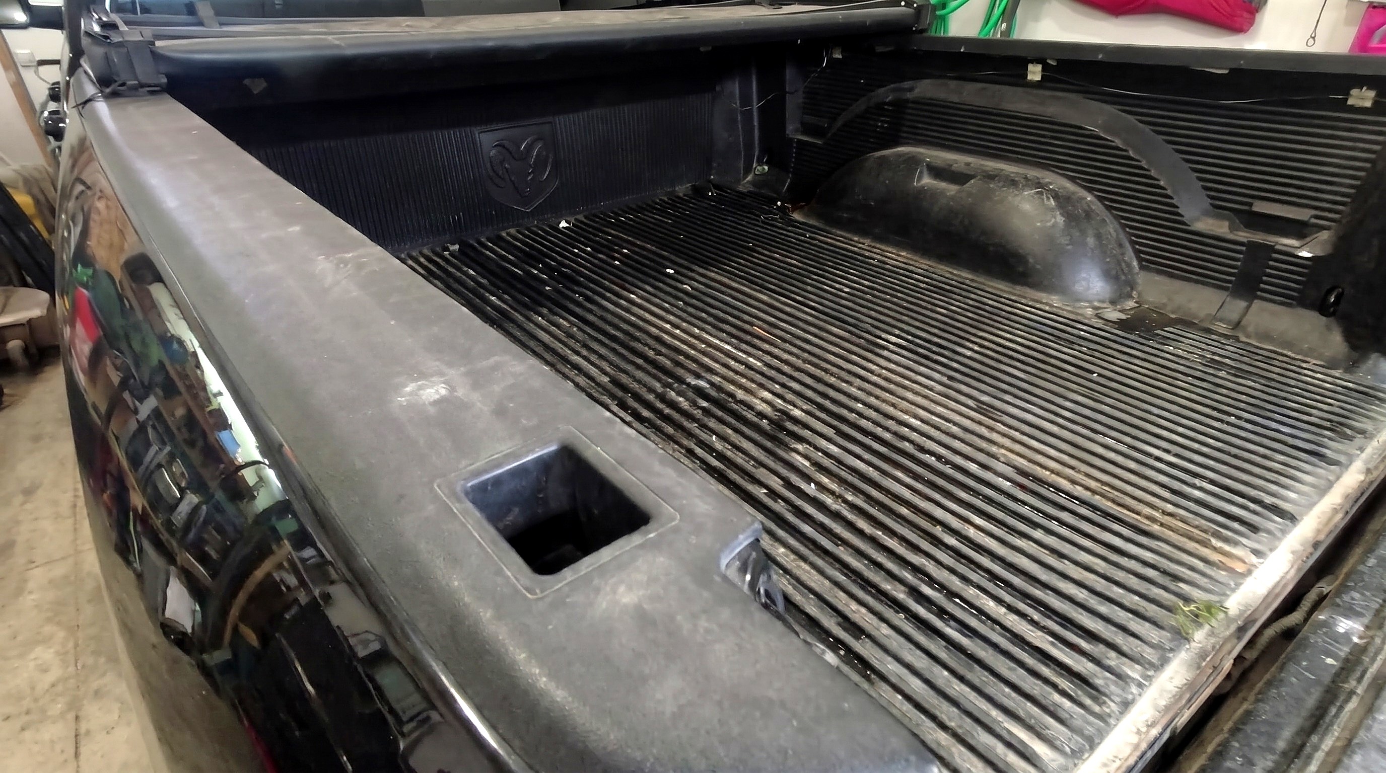
Parts in this step: (B) 5-pin relay and pigtail plug, (D) Truck bed LED light strand
You'll need: Wire Crimper and Cutter, Soldering Iron, LED Truck Bed Light Strand, 5-Pin Automotive Relay with Pigtail Harness, Electrical Wire, Corrugated Split Wire Loom, Zip Ties, Butt Connectors, Electrical Tape
- 5.1 Encapsulate the 12V wires in split loom and zip-tie under the truck
- Splice 16 AWG red wire to terminal 87 (blue wire) on the 5-pin relay and pigtail plug (B) with a butt connector.
- Put the 16 AWG positive wire (terminal 87) and 16 AWG black battery negative wire inside corrugated split wire loom.
- Drop the enclosed wires below the firewall under the truck.
- Secure the split wire loom along the underside of the truck frame to the rear bed corner using zip ties.
- 5.2 Fish the wires up the bed sidewall and splice to the LED light strand
- Mount 8-pod truck bed LED light strand (D) under the bed rails: three pods per side, two across the front bulkhead.
- Feed the LED strand lead through the upper rear bed corner gap into the stake pocket.
- Fish underbody 16 AWG positive and negative wires up inside the rear sidewall into the same stake pocket.
- Join positive to positive and negative to negative with butt connectors, wrap in electrical tape, and tuck into the pocket.
Key measurements
- LED count: 1 strand of 8 squares, 6 LEDs per square (3 left, 3 right, 2 front).
- Underbody power and ground wire: 16 AWG red and black.
- Tip: House final butt splices in the rear bed stake pocket so no connections sit exposed to weather.
- Heads up: Zip-tie split wire loom high under the truck, clear of moving parts, hot exhaust, and road debris.
Before you move on: Check underbody wiring is in split loom, zip-tied tight, and both stake pocket splices are taped.
Finishing
Last Touches
- Tuck taped LED splices deep in the rear stake pocket, away from cargo.
- Snap the driver-side door step plate back over the cab wiring harness.
- Trim zip-tie tails under the truck frame.
Care
- Check underbody zip ties and split plastic loom seasonally for road damage.
- Check the battery ring terminals and inline fuse holder for corrosion during routine maintenance.
Alternatives
- Solder and heat-shrink splices instead of using crimp butt connectors and electrical tape.
- Use lever-style Wago tap connectors for tool-free splices with minimal exposed area.
Commission & test
| Check | What you should see | If not |
|---|---|---|
| Open a cab door and check truck bed LED light strand (D). | All 8 LED pods (6 LEDs per square) light immediately with the cab dome light. | Check the battery 10 A or 15 A inline blade fuse, T-tap pierce through the dome light wire insulation, and tight battery ring terminals. |
| Close all cab doors until the cab dome light turns off. | The relay opens the circuit; truck bed LED lights shut off with the dome light. | If bed lights turn on when the dome light shuts off, move the LED positive wire from terminal 87a to terminal 87. |
| With cab doors closed, turn on the interior dome light via the dashboard dial. | The dome light circuit sends 12 V to relay terminal 86, switching truck bed lights on from the cab. | Check the blue male blade connector seats firmly in the T-tap under the step plate. |
| Leave a cab door open 15 minutes to test the dome light shutoff timer. | Both cab dome and truck bed LED lights turn off after 15 minutes to protect the battery. |
These Specs are built from Indy Farm Life's video “Truck Bed LED Lights Wired with a Dome Light Relay”. Open the Truck Bed LED Lights Wired with a Dome Light Relay project page.
